Zilog Z16F2810 User Manual
Page 170
SLL Instruction
UM018809-0611
154
ZNEO
®
CPU Core
User Manual
SLL
Definition
Shift Left Logical
Syntax
SLL dst, src
Operation
Description
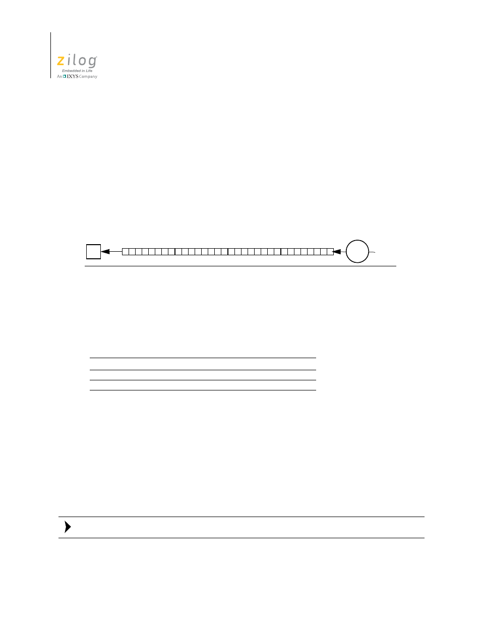
The destination operand contents shift left logical by the number of bit positions (0–31)
specified in bits [4:0] of the source operand. On each bit shift iteration, the value of the
most significant bit moves into the Carry (
C
) flag, and Bit 0 clears to 0. The source register
value is not changed.
Flags
Flags are set based on the 32-bit destination register value.
7
6
5
4
3
2
1
0
C
Z
S
V
B
CIRQE IRQE
*
*
*
*
0
–
–
–
Legend
C
= Set to 1 if the last bit shifted out is 1; otherwise set to 0.
Z
= Set to 1 if the result is zero; otherwise, set to 0.
S
= Set to 1 if the result msb is 1; otherwise set to 0.
V
= Set to 1 if the Carry and Sign flags are different; otherwise set to 0.
B
= Cleared to 0.
CIRQE
= No change.
IRQE
= No change.
C
0
src
dst
31
0
Note: