Doorbell module signals, Generating a doorbell message – Altera RapidIO II MegaCore Function User Manual
Page 88
4–46
Chapter 4: Functional Description
Logical Layer Interfaces
RapidIO II MegaCore Function
August 2014
Altera Corporation
User Guide
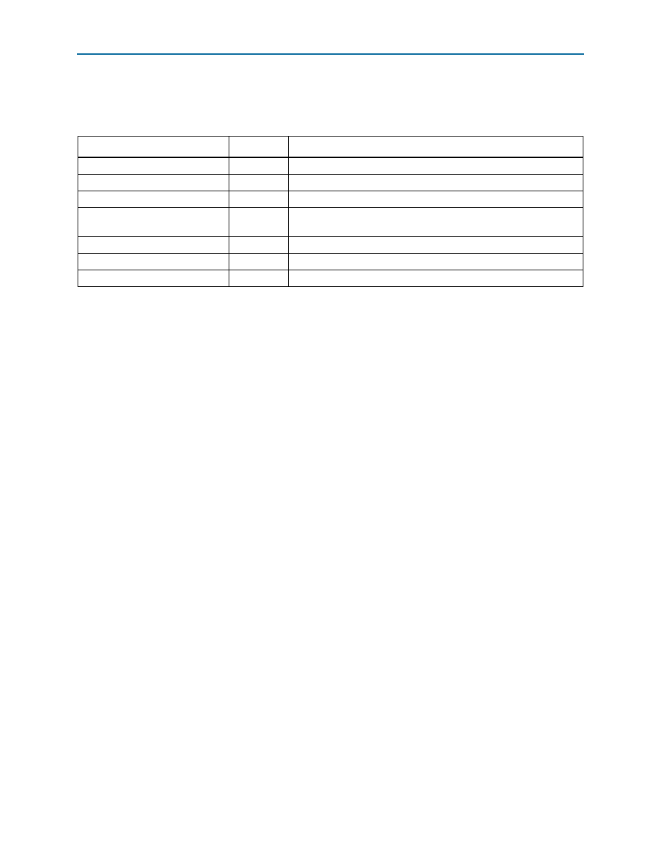
Doorbell Module Signals
lists the Doorbell module interface signals.
Generating a Doorbell Message
To generate a DOORBELL request packet on the RapidIO serial interface, follow these
steps, using the set of registers described in
“Doorbell Message Registers” on
1. Optionally enable interrupts by writing the value 1 to the appropriate bit of the
Doorbell
Interrupt Enable register (
2. Optionally enable confirmation of successful outbound messages by writing 1 to
the COMPLETED bit of the Tx Doorbell Status Control register (
3. Set up the PRIORITY field of the Tx Doorbell Control register (
).
4. Write the Tx Doorbell register (
) to set up the DESTINATION_ID and
Information
fields of the generated DOORBELL packet format.
1
Before writing to the Tx Doorbell register you must be certain that the Doorbell
module has available space to accept the write data. Ensuring sufficient space exists
avoids a waitrequest signal assertion due to a full FIFO. When the waitrequest
signal is asserted, you cannot perform other transactions on the DOORBELL Avalon-MM
slave port until the current transaction is completed. You can determine the combined
fill level of the staging FIFO and the Tx FIFO by reading the Tx Doorbell Status
register (
). The total number of Doorbell messages stored in the staging
FIFO and the Tx FIFO, together, is limited to 16 by the assertion of the
drbell_s_waitrequest
signal.
After a write to the Tx Doorbell register is detected, internal control logic generates
and sends a Type 10 packet based on the information in the Tx Doorbell and Tx
Doorbell
Control registers. A copy of the outbound DOORBELL packet is stored in the
Acknowledge RAM.
When the response to an outbound DOORBELL message is received, the corresponding
copy of the outbound message is written to the Tx Doorbell Completion FIFO (if
enabled), and an interrupt is generated (if enabled) on the Avalon-MM slave interface
by asserting the drbell_s_irq signal of the Doorbell module. The ERROR_CODE field in
the Tx Doorbell Completion Status register (
) indicates successful or error
completion.
Table 4–22. Doorbell Module Interface Signals
Signal
Direction
Description
drbell_s_waitrequest
Output
Doorbell module wait request.
drbell_s_write
Input
Doorbell module write request.
drbell_s_read
Input
Doorbell module read request.
drbell_s_address[3:0]
Input
Doorbell module address bus. The address is a word address, not a
byte address.
drbell_s_writedata[31:0]
Input
Doorbell module write data bus.
drbell_s_readdata[31:0]
Output
Doorbell module read data bus.
drbell_s_irq
Output
Doorbell module interrupt.