Maintenance packet error handling, Maintenance packet error handling –43 – Altera RapidIO II MegaCore Function User Manual
Page 85
Chapter 4: Functional Description
4–43
Logical Layer Interfaces
August 2014
Altera Corporation
RapidIO II MegaCore Function
User Guide
The RapidIO II IP core generates read requests on the Maintenance Avalon-MM
master interface when it receives Type 8 MAINTENANCE Read packets on the RapidIO
link with the following properties:
■
ttype
has the value of 4'b0000, indicating a MAINTENANCE Read request
■
config_offset
has a value that indicates an address outside the range of the
RapidIO II IP core internal register set
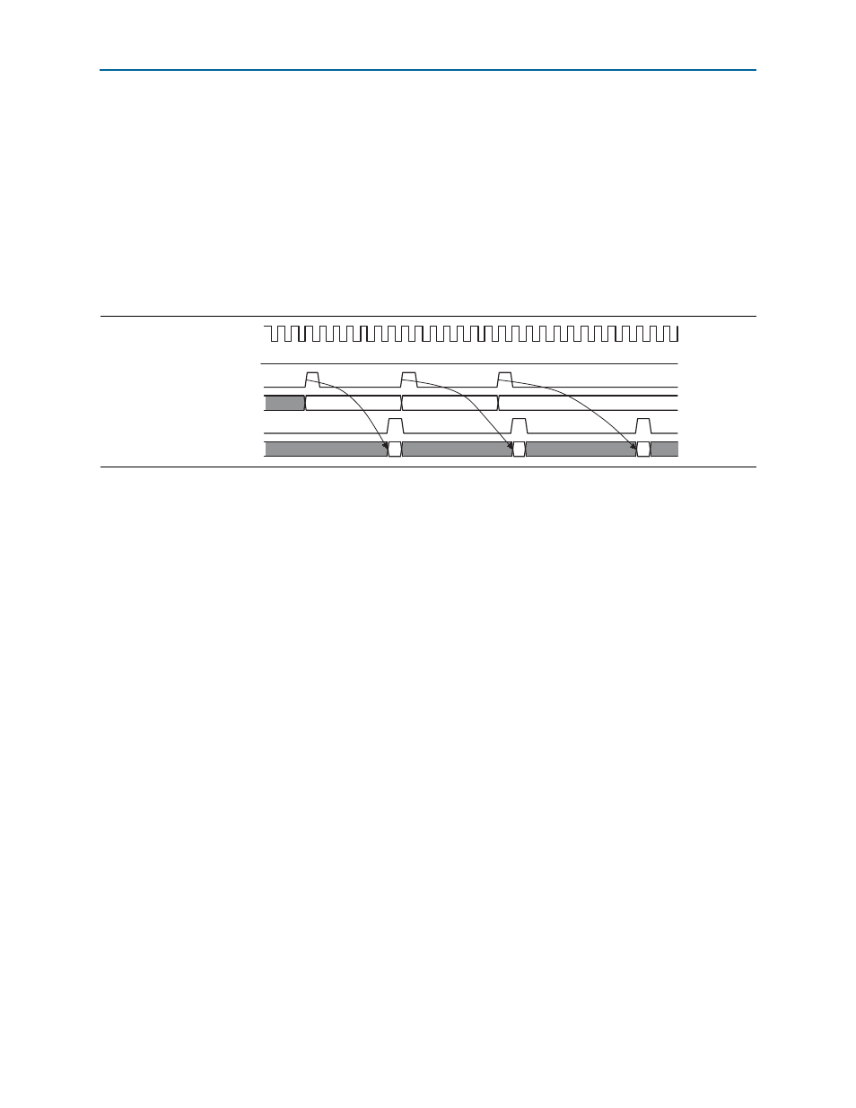
Figure 4–19
shows the signal relationships for an example sequence of three read
requests that the RapidIO II IP core presents on the Maintenance Avalon-MM master
interface, and the data responses from user logic.
In the first active clock cycle, the RapidIO II IP core indicates the start of a read request
by asserting the usr_mnt_read signal. Simultaneously, the IP core presents the target
address on the usr_mnt_address address bus.
User logic presents the read responses on the Maintenance Avalon-MM master
interface by asserting the usr_mnt_readdatavalid signal while presenting the data on
the usr_mnt_data bus.
Maintenance Packet Error Handling
The Maintenance Interrupt register (at 0x10080) and the Maintenance Interrupt
Enable
register (at 0x10084), described in
, determine the
error handling and reporting for MAINTENANCE packets.
The following errors can also occur for MAINTENANCE packets:
■
A MAINTENANCE read or MAINTENANCE write request time-out occurs and a
PKT_RSP_TIMEOUT
interrupt (bit 24 of the Logical/Transport Layer Error Detect
CSR, described in
) is generated if a response packet is not
received within the time specified by the Port Response Time-Out Control
register (
■
The IO_ERROR_RSP (bit 31 of the Logical/Transport Layer Error Detect CSR) is set
when an ERROR response is received for a transmitted MAINTENANCE packet.
For information about how the time-out value is calculated, refer to
.
For more information about the error management registers, refer to
Figure 4–19. Read Transfers on the Maintenance Avalon-MM Master Interface
usr_mnt_read
usr_mnt_address
usr_mnt_readdatavalid
usr_mnt_readdata
system clock
0x10
0x14
0x18
usr_mnt_waitrequest