Register-related signals, Logical and transport layer signals, Avalon-mm interface signals – Altera RapidIO II MegaCore Function User Manual
Page 133: Register-related signals –9, Logical and transport layer signals –9, Avalon-mm interface signals –9
Chapter 5: Signals
5–9
Logical and Transport Layer Signals
August 2014
Altera Corporation
RapidIO II MegaCore Function
User Guide
Register-Related Signals
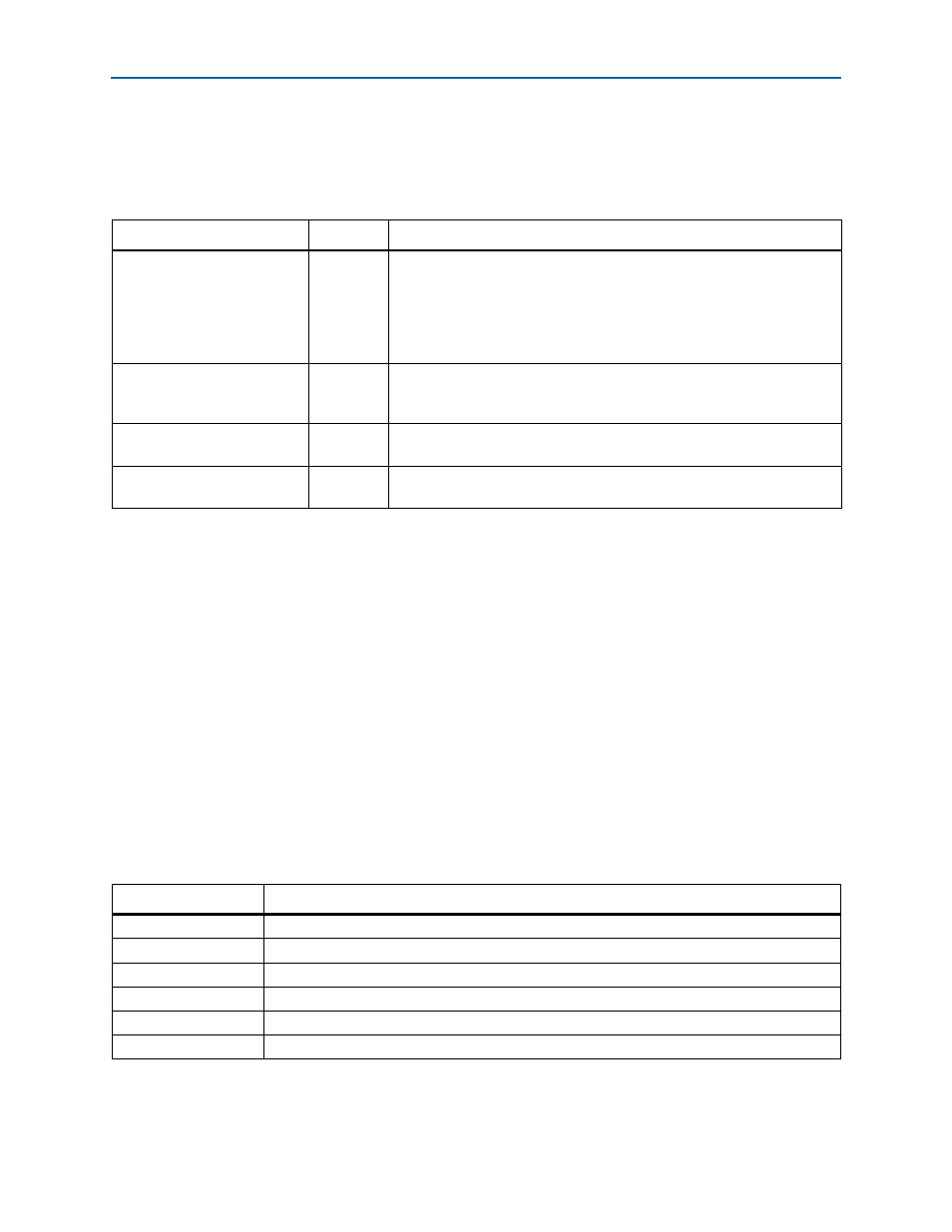
Table 5–9
lists the Physical layer register-related signals. These signals are output
signals that reflect useful register field values.
Logical and Transport Layer Signals
This section shows you the signals used by the Transport layer and the Logical layer
modules of the RapidIO IP core. For a list of descriptions of the signals used and
generated by the Physical layer, see
“Physical Layer Signals” on page 5–2
Avalon-MM Interface Signals
This section tells you where you can find information about the signals for the
Avalon-MM interfaces. Signals on Avalon-MM interfaces are in the Avalon system
clock domain.
f
for details.
lists the location of the signal lists and descriptions for the Logical layer
Avalon-MM interfaces.
Table 5–9. Register-Related Signals
Signal
Direction
Description
master_enable
Output
This output reflects the value of the Master Enable bit of the Port
General
Control CSR (
), which indicates whether
this device is allowed to issue request packets. If the Master Enable bit is
not set, the device may only respond to requests. User logic connected to
the Avalon-ST pass-through interface should honor this value and not cause
the Physical layer to issue request packets when it is not allowed.
time_to_live[15:0]
Output
This output reflects the value of the TIME_TO_LIVE field of the Packet
Time-to-Live
CSR (
), which is the maximum
time duration that a packet is allowed to remain in a switch device
base_device_id[7:0]
Output
This output reflects the value of the Base_deviceID field in the Base
Device ID
CSR (
).
large_base_device_id
[15:0]
Output
This output reflects the value of the Large_base_deviceID field in the
Base Device ID
).
Table 5–10. Avalon-MM Interface Signals
Interface
Location of Signal Table
Register Access
Refer to
.
Input/Output master
Refer to
Input/Output slave
Refer to
Maintenance slave
Refer to
.
Maintenance master
Refer to
.
Doorbell
Refer to
.