6 process data, base unit, Allocation table of the virtual inputs and outputs, Process data, base unit – Pilz PNOZ m B0 User Manual
Page 52
Modbus/TCP
Operating Manual PNOZmulti 2 Communication Interfaces
1002971EN02
52
6.4.5
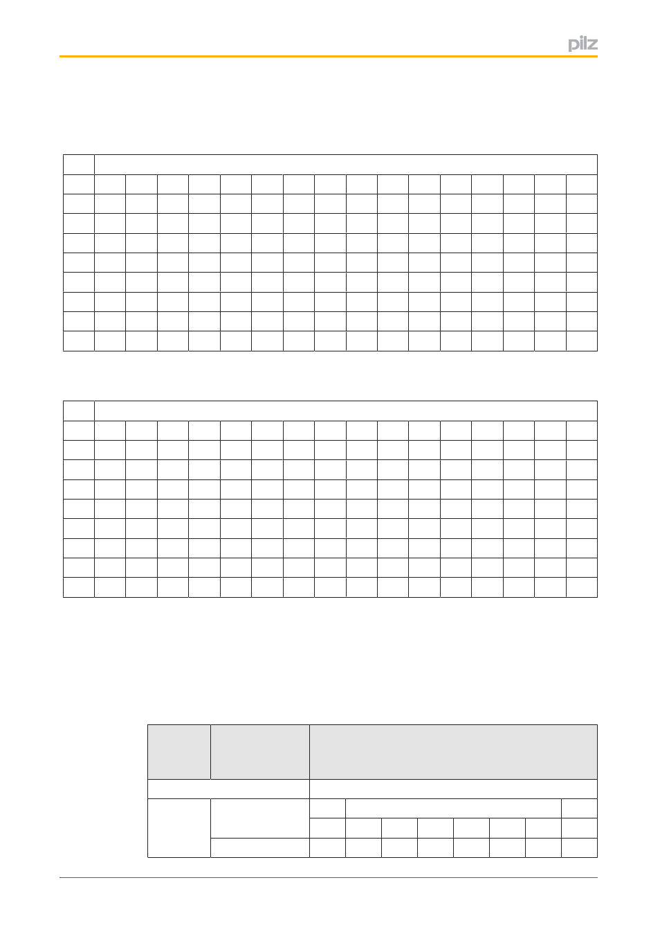
Allocation table of the virtual inputs and outputs
Addressing the virtual inputs (coils) in Registers 0 to 7.
Virtual inputs
15
14
13
12
11
10
9
8
7
6
5
4
3
2
1
0
0
15
14
13
12
11
10
9
8
7
6
5
4
3
2
1
0
1
31
30
29
28
27
26
25
24
23
22
21
20
19
18
17
16
2
47
46
45
44
43
42
41
40
39
38
37
36
35
34
33
32
3
63
62
61
60
59
58
57
56
55
54
53
52
51
50
49
48
4
79
78
77
76
75
74
73
72
71
70
69
68
67
66
65
64
5
95
94
93
92
91
90
89
88
87
86
85
84
83
82
81
80
6
111
110
109
108
107
106
105
104
103
102
101
100
99
98
97
96
7
127
126
125
124
123
122
121
120
119
118
117
116
115
114
113
112
Allocation of virtual inputs i0, i1 ... i127 to the Bits in Registers 0 to 7
Addressing the virtual outputs (discrete inputs) in Registers 512 to 519.
Virtual outputs
15
14
13
12
11
10
9
8
7
6
5
4
3
2
1
0
512
15
14
13
12
11
10
9
8
7
6
5
4
3
2
1
0
513
31
30
29
28
27
26
25
24
23
22
21
20
19
18
17
16
514
47
46
45
44
43
42
41
40
39
38
37
36
35
34
33
32
515
63
62
61
60
59
58
57
56
55
54
53
52
51
50
49
48
516
79
78
77
76
75
74
73
72
71
70
69
68
67
66
65
64
517
95
94
93
92
91
90
89
88
87
86
85
84
83
82
81
80
518
111
110
109
108
107
106
105
104
103
102
101
100
99
98
97
96
519
127
126
125
124
123
122
121
120
119
118
117
116
115
114
113
112
Allocation of virtual outputs o0, o1 ... o127 to the Bits in Registers 512 to 519.
6.4.6
Process data, base unit
The table below describes the Modbus/TCP data areas containing the base unit's process
data.
Relevant areas for the data are defined in the Modbus/TCP data areas Discrete Inputs (1x)
and Input Register (3x). Read access is available to these data areas.
Register
(3x)
Coil/
Discrete Input
(1x)
Content
State of the inputs on the base unit
1024
16391 … 16384
Bit 7
…
Bit 0
i7
i6
i5
i4
i3
i2
i1
i0
16399 … 16392
i15
i14
i13
i12
i11
i10
i9
i8