4 data areas, 1 overview, Data areas – Pilz PNOZ m B0 User Manual
Page 47: Overview
Modbus/TCP
Operating Manual PNOZmulti 2 Communication Interfaces
1002971EN02
47
6.4
Data areas
6.4.1
Overview
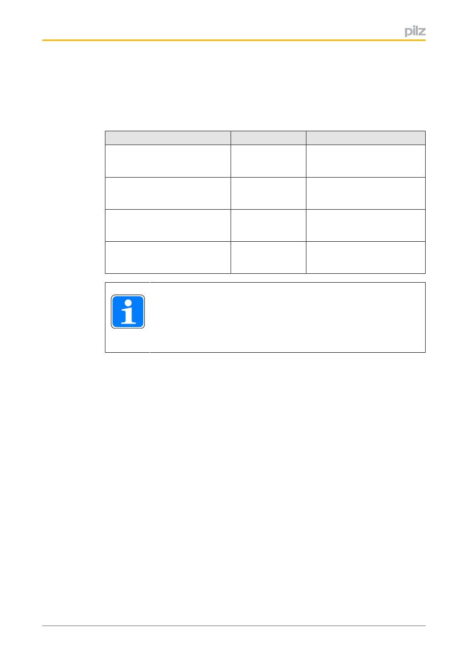
A configurable control system PNOZmulti 2 supports the following Modbus/TCP data areas:
Data area
Modbus syntax
Example
Coils (Bit)
0x00000 … 0x65535
[read/write]
0x[xxxxx]
0x00031
(virtual input i31)
Discrete Inputs (Bit)
1x00000 … 1x65535
[read only]
1x[xxxxx]
1x08193
(virtual output o1)
Input Register (Word/16 Bits)
3x00000 … 3x65535
[read only]
3x[xxxxx]
3x00002
(virtual inputs 32 ... 47)
Holding Register (Word/16 Bits)
4x00000 … 4x65535
[read/write]
4x[xxxxx]
4x04108
(project name, 1st character)
INFORMATION
Addressing for PNOZmulti systems starts at “0”. On devices from other
manufacturers, addressing can start at “1”.
Please refer to the operating manual provided by the relevant manufacturer.
Data can be accessed via various Modbus/TCP data areas.
The tables below show the relationship between Modbus/TCP data areas and the content
of the data areas.