Appendix – Pilz PNOZ m B0 User Manual
Page 156

Appendix
Operating Manual PNOZmulti 2 Communication Interfaces
1002971EN02
156
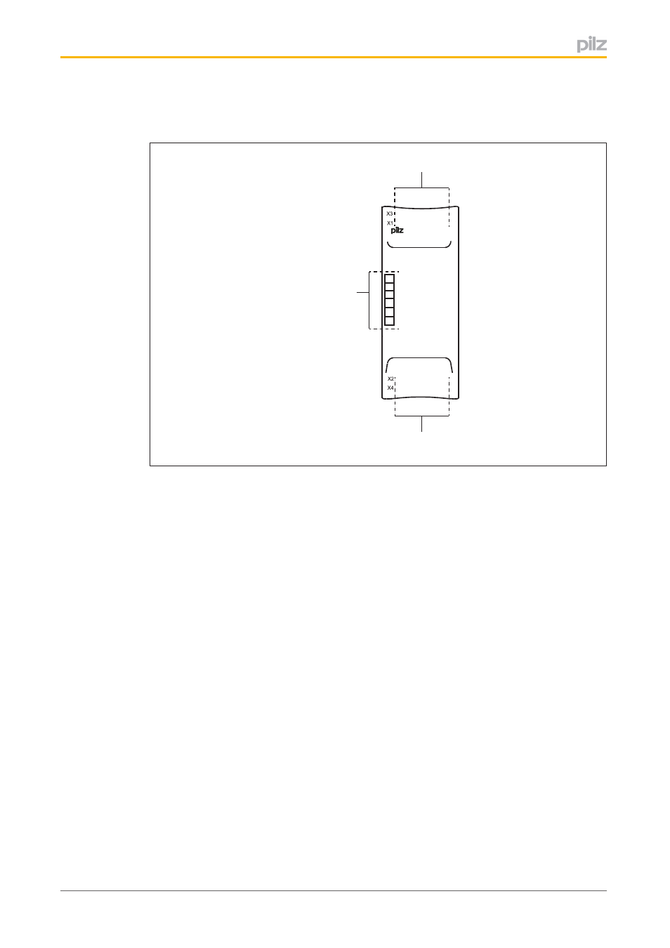
The assignment of the I/OLEDs and system LEDs to LEDs on the righthand expansion
modules corresponds to the format shown in the following diagram.
0 1 2 3
4 5 6 7
8 9 10 11
12 13 14 15
IO-LED
IO-LED
System-LED
PNOZ m EF ...
LED 0
LED 1
LED 2
LED 3
LED 4
LED 5
Fig.: LEDs on expansion modules on the righthand side
This manual is related to the following products:
