3 data transfer limits, 4 input and output data, watchdog, Data transfer limits – Pilz PNOZ m B0 User Manual
Page 49: Input and output data, watchdog
Modbus/TCP
Operating Manual PNOZmulti 2 Communication Interfaces
1002971EN02
49
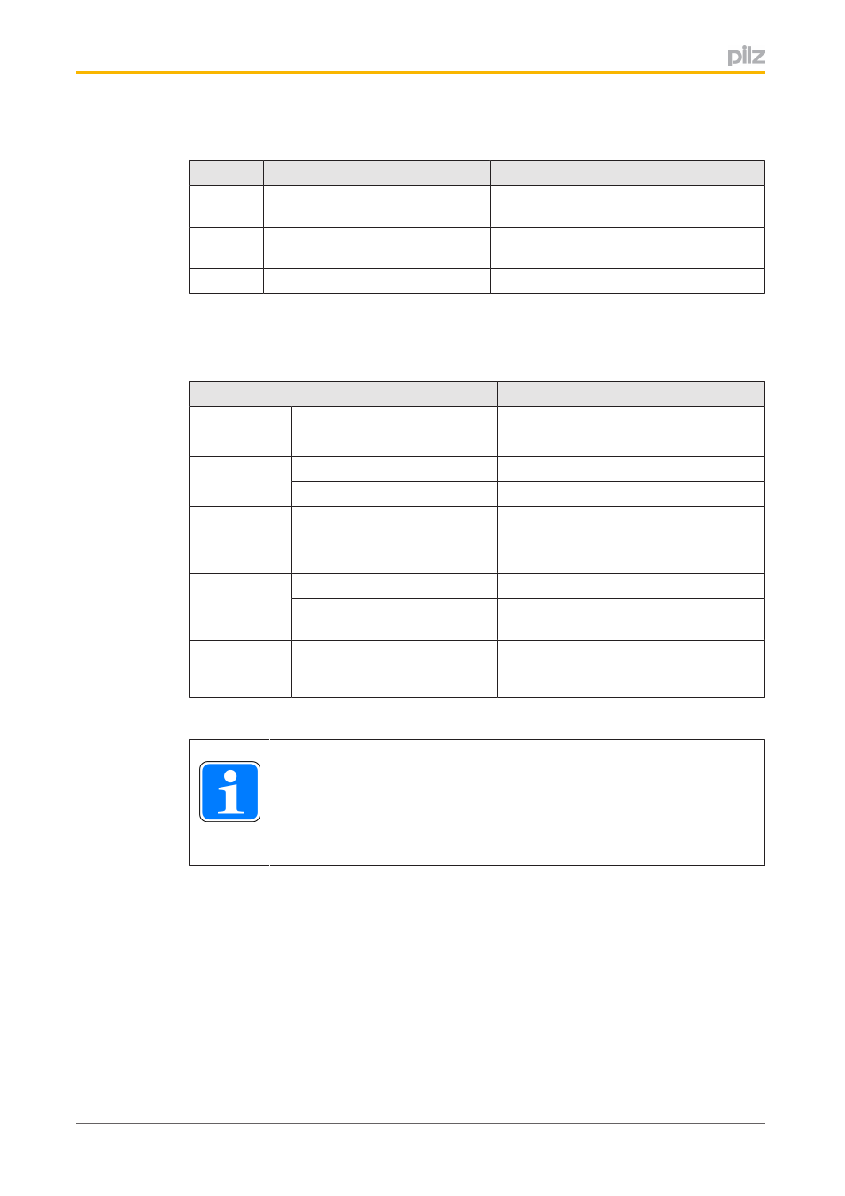
Error codes on Modbus/TCP
Code
Name
Description
01
Invalid function
The function code in the enquiry is not
supported.
02
Invalid data address
The data address received in the enquiry
is outside the memory range.
03
Invalid data
Invalid data requested.
6.4.3
Data transfer limits
The following table contains information on the data length per telegram that is supported:
Data transfer
Data length per telegram
Read data
(Bit)
FC 01 (Read Coils)
1 … 2000
FC 02 (Read Discrete Inputs)
Read data
(Bit)
FC 05 (Write Single Coil)
1 Bit
FC 15 (Write Multiple Coils)
1 … 1968
Read data
(Word)
FC 03 (Read Holding Re
gisters)
1 … 125
FC 04 (Read Input Register)
Write data
(Word)
FC 06 (Write Single Register)
1 Word
FC 16 (Write Multiple Re
gisters)
1 … 123 Words
Read and
write data
(Word)
FC 23 (Read/Write Multiple
Registers)
Read 1 … 125 Words
Write 1 … 121 Words
INFORMATION
There may be some restrictions in data length, depending on the device that
is used. Please refer to the information stated in the operating manual of the
device you are using.
6.4.4
Input and output data, watchdog
The table below describes the Modbus/TCP data areas that contain the current state of the
virtual inputs of the PNOZmulti 2. These are the virtual inputs that can be set by the user.
Relevant areas for the data are defined in each Modbus/TCP data area (Coils (0x), Discrete
Inputs (1x), Input Register (3x), Holding Register (4x)). Read/write access will depend on
the Modbus/TCP data area.