Module locations, Module locations -6, Module and fan installation – Carrier Access Broadmore 1750 User Manual
Page 88
5-6
Broadmore 1750 - Release 4.6
Module and Fan Installation
Module Locations
Module Locations
Obtain the office records showing the module slot installation locations for this chassis.
The network design engineer will assign module slots to ensure proper system
operation. (For detailed system design and configuration information, see “System
Planning Factors” on page
.)
The Broadmore 1750 chassis is designed for modules to go into specific slots to support
various user requirements and cell bus bandwidths. As a minimum requirement, the
module slot installations must conform to the guidelines on the following page.
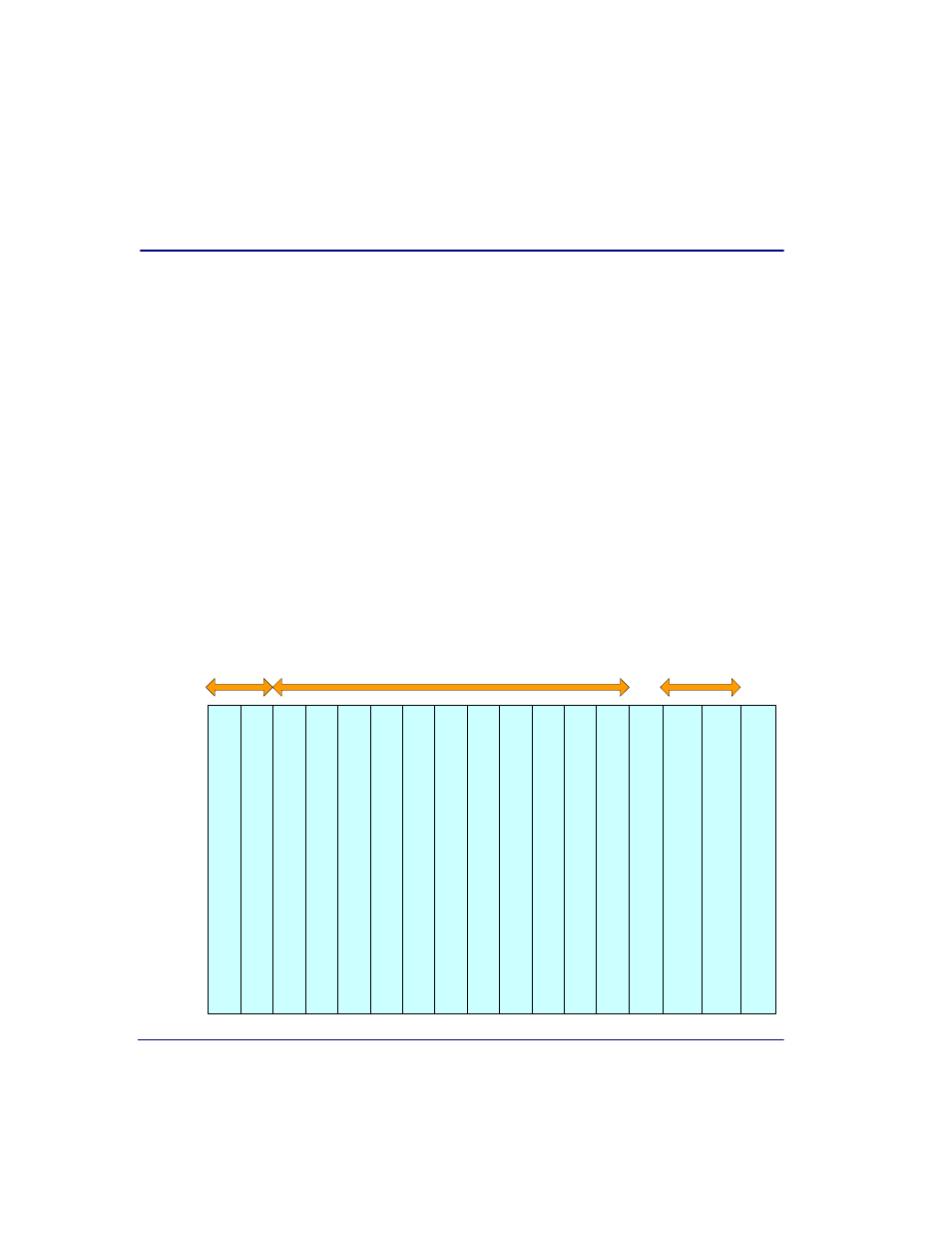
The Broadmore 1750 is normally configured with redundant CPUs, redundant OC-12c
NIMs, and five Unstructured DS3 SAMs providing 1:4 protection, as shown in the
figure below. Other configurations are possible (contact factory for details).
The Broadmore 1750 system architecture is based upon a midplane design allowing
modules to be installed from the front and rear of the chassis. There are 17 vertical slots
as viewed from the front with the cover removed, as shown below. Input/Output
Module (IOM) slots on the rear panel are numbered in the reverse order, so that they
align with the module slots on the front panel. Each NIM, SAM, CPU, and APM
requires a matching IOM installed in the rear.
A
B
C
D
E
F
G
H
J
K
L
M
N
P
CPU
Q
CPU
R
APM
NIM Slots
SAM Slots
CPU Slots
PR
O
T
E
C
T
IO
N
S
A
M
OC
-1
2
c
N
IM
OC
-1
2
c
N
IM
u
D
S
3
-3
or
uE
3
-3
S
A
M
CP
U
CP
U
AP
M
u
D
S
3
-3
or
uE
3
-3
S
A
M
u
D
S
3
-3
or
uE
3
-3
S
A
M
u
D
S
3
-3
or
uE
3
-3
S
A
M