Carrier Access Broadmore 1750 User Manual
Page 178
7-64
Broadmore 1750 - Release 4.6
Configuration
PVC Connection
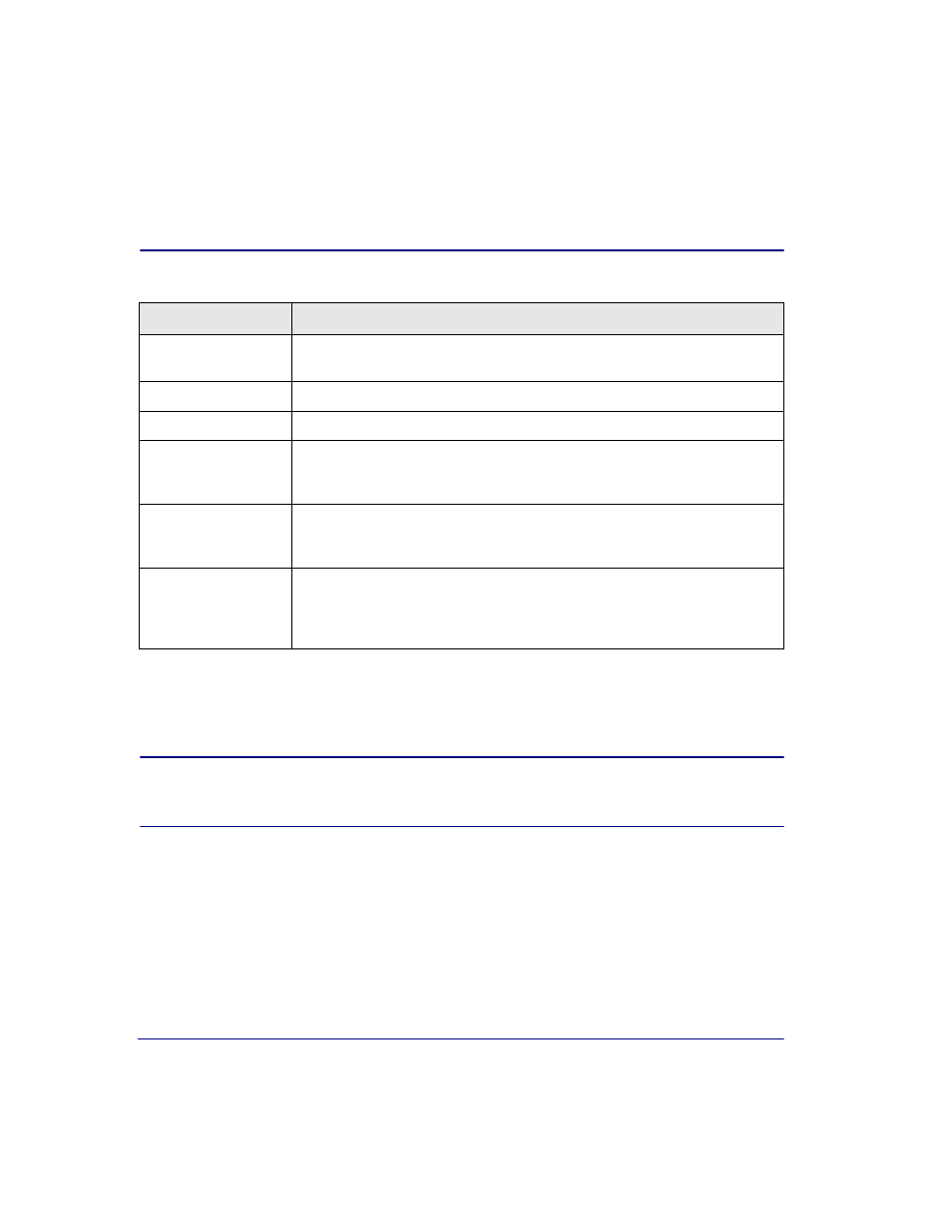
Table 7-18: PVC Configuration Items
The VPI/VCI are locally significant and need to match on both ends of the
PVC. Therefore the VPI/VCI must be provisioned identically on the ATM
switch port.
NOTE:
The transmit and receive VPI/VCI must be configured through
the ATM switch. The procedure for this will vary by switch. Consult the ATM
switch documentation to accomplish this configuration.
Item
Definition
Connection Name
Press the space bar to select Connection Name and type a descriptive identifier (For
example, test port 2).
Local Slot
The Local Slot is the chassis slot.
Local Port Number
Port number depends on the configuration.
Local Channel Map
Channel map depends on the configuration. Channel map only applies to the
Structured DS3 SAMs. There is no channel mapping for the Unstructured DS3 or
Unstructured E3, and this value will be displayed as N/A.
VP/VC (Transmit/
Receive)
The maximum settings for VP/VC are allocated using the Max VP/VC feature in
System Services (see
). Table 7-1 on page 7-20
shows the valid VP/VC values.
CDV
Cell Delay Variation (CDV) is the difference between the expected arrival time and
the actual arrival time of the next cell. This value is expressed in number of cells.
The value can vary from 0 to 255. An initial value of 80 to 100 cells is
recommended.