Alarm port connections, Alarm port connections -5 – Carrier Access Broadmore 1750 User Manual
Page 103
Broadmore 1750 - Release 4.6
6-5
Electrical
Installation
Alarm Port Connections
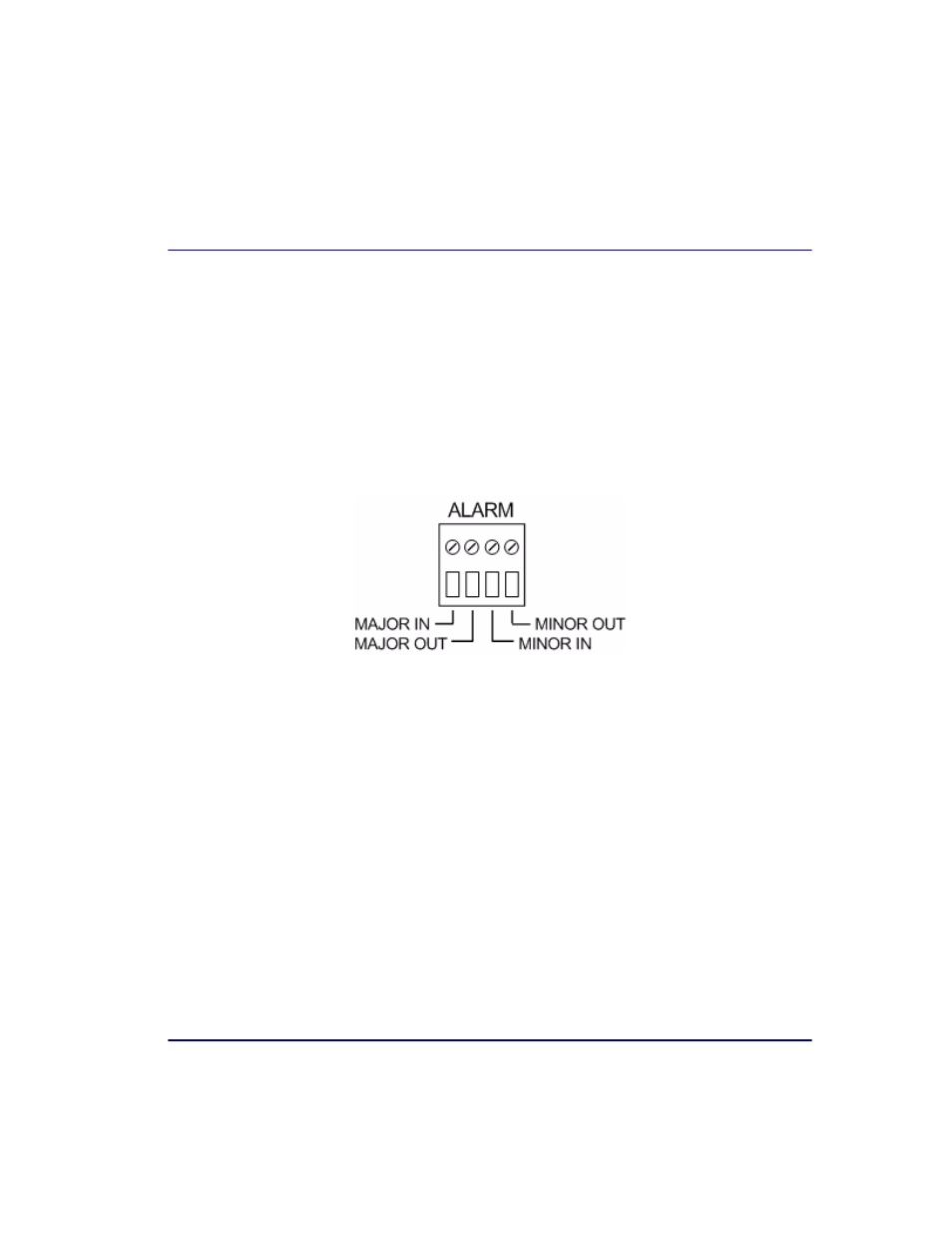
Alarm Port Connections
Alarms are sent to the control console and the system log. LEDs display alarm
conditions. Additionally, the Broadmore 1750 has an alarm port on the chassis rear for
connection to the user’s
remote indicators. The alarm port is a four-wire terminal block
providing form “C” relay contact closure signals. Two wires are labeled “Major” (in
and out) and two are labeled “Minor” (in and out) as shown below. The alarm connector
on the lower back of the chassis is shown below. The connector is a compression type
in which the wire is inserted in the lower opening and the compression screw above is
tightened to secure the wire. A small flathead screwdriver is required to secure the
wires.
1. Run the alarm cables to the connection point on the chassis rear as shown
above.
2. Insert the cable wires and tighten the compression screws to secure the wires.