C-more controller for benchmark, innovation & kc – AERCO C-More Controls Manual June 2010 User Manual
Page 43
C-More Controller for Benchmark, Innovation & KC
USER MANUAL
04/22/14
AERCO International, Inc. • 100 Oritani Dr. • Blauvelt, New York 10913
Page 43 of 162
OMM-0032_0E
Phone: 800-526-0288
GF-112
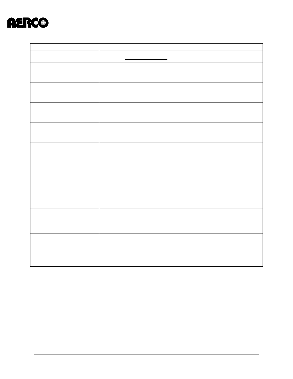
Table 3-1: Menu Item Descriptions - Continued
MENU LEVEL & OPTION
DESCRIPTION
Diagnostic Menu
Exhaust Tmp Sens
Allows the Enabling or Disabling of the alternating warning and fault
messages on the VFD display for EXHAUST TEMPERATURE
Default is Disabled. (See Table 3-1A)
In Wtr Tmp Sens
Allows the Enabling or Disabling of the alternating warning and fault
message on the VFD Display for INLET WATER TEMPERATURE.
Default is Disabled. (See Table 3-1A)
In Gas Press Sen
Allows the Enabling or Disabling of the alternating warning and fault
message on the VFD Display for INLET GAS PRESSURE. Default
is Disabled. (See Table 3-1A)
Gas Plate dp Sen
Allows the Enabling or Disabling of the alternating warning and fault
message on the VFD Display for GAS PLATE DIFFERENTIAL.
Default is Disabled. (See Table 3-1A)
In Water Flw Sen
Allows the Enabling or Disabling of the alternating warning and fault
message on the VFD Display for INLET WATER FLOW. Default is
Disabled. (See Table 3-1A)
Display Test**
Allows testing of the front panel LED indicators, 3-character, 7-
segment LED Outlet Temperature display and 20-segment LED
Bargraph.
Keypad Test**
Allows testing of the operational status of each front panel key. The
VFD will display the name of each key as it is pressed.
Relay Test**
Allows user to force relay outputs ON or OFF. The relays tested
include: Igniter, Blower, Pump, Aux and Fault relay.
Switch Test**
Allows the ON/OFF status of all switch inputs to be viewed. These
switches include: Exhaust, SSOV, Blower Proof, Ignition, Over-
Temp, Low Gas Pres, Hi Gas Pres, Water Lev, Rem Int, Front Pnl,
Delayed Int and Purge switches.
Stepper Test**
Allows adjustment of the Air/Fuel Valve stepper motor position
using the ▲ and ▼ keys. The Bargraph display will light to indicate
the current stepper motor position.
Sensor Log Int
Allows the Sensor Log Interval to be set to: 1 Min, 5 Min, 15 Min,
30 Min, 1 Hr, 6 Hrs, 12 Hrs or 24 Hrs. Default setting is 30 Min.
**Not Adjustable via RS232 Serial Port