3 bst modbus network wiring, Bst modbus network wiring, C-more controller for benchmark, innovation & kc – AERCO C-More Controls Manual June 2010 User Manual
Page 105
C-More Controller for Benchmark, Innovation & KC
USER MANUAL
04/22/14
AERCO International, Inc. • 100 Oritani Dr. • Blauvelt, New York 10913
Page 105 of 162
OMM-0032_0E
Phone: 800-526-0288
GF-112
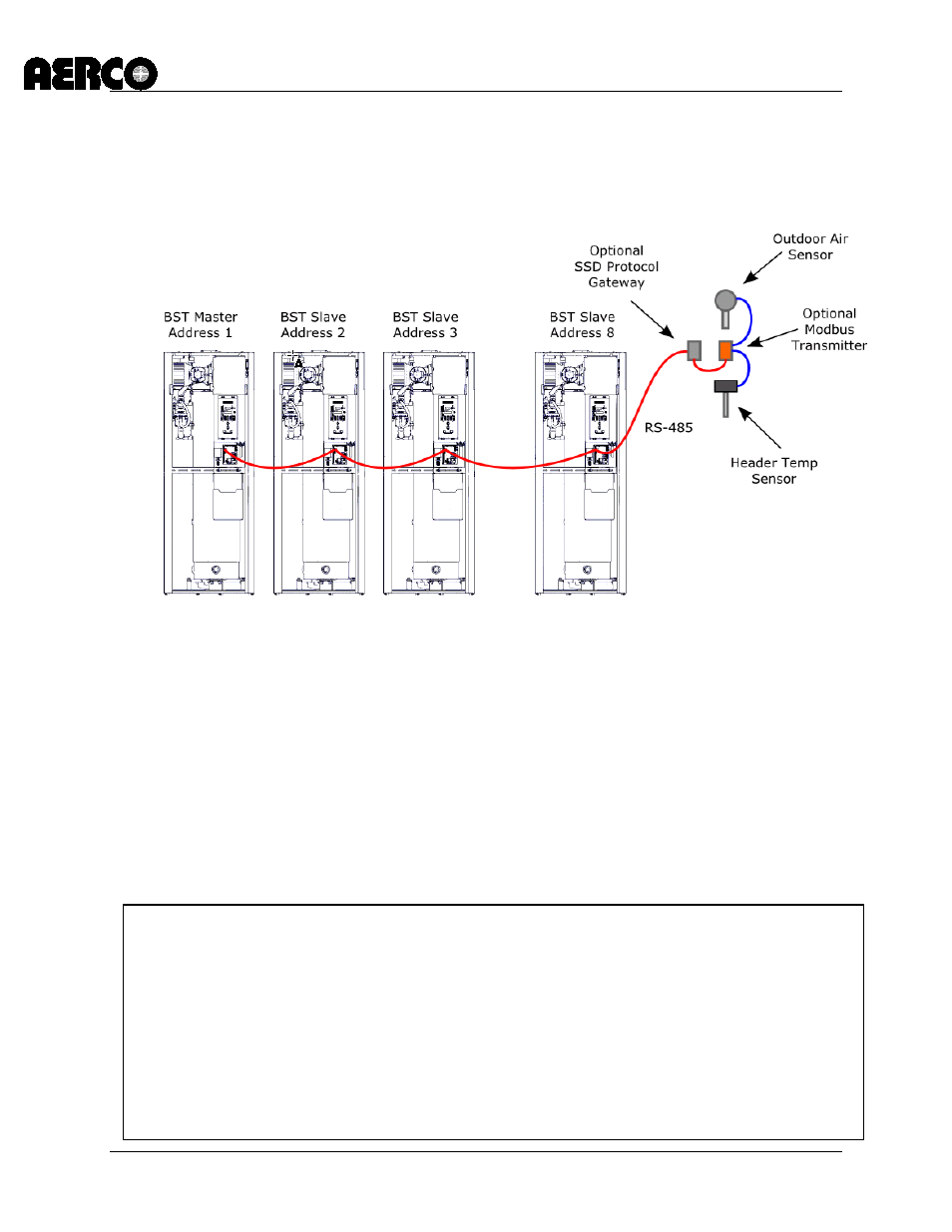
9.3 BST Modbus Network Wiring
As previously mentioned, all units being controlled by the BST will be connected to a RS485
Modbus Network. All Modbus networks are wired in a daisy-chain configuration using a
Master/Slave scenario as shown in Figure 9-3.
NOTE: The BST master unit does not have to be address 1. Master unit is also an internal slave.
Figure 9.3: Typical Daisy-Chain Modbus/RS485 Network
Any one of the C-More BST units included in the Modbus network can be the Master. However,
it is recommended that you decide which unit will be the Master and which will be the last unit
on the daisy-chain prior to performing the wiring connections. This will simplify wiring
connections and Modbus address assignments.
Modbus network wiring connections must be made using shielded twisted-pair wiring, (18 – 24
AWG) such as Belden #9841, #3105A, #8760, or equivalent. The Modbus wiring connections
are made at the RS485 COMM terminals on the I/O board included with each C-more Control
System.
Connect the Modbus wiring as follows:
Modbus Network Wiring
1. Starting at the first unit, connect the twisted, shielded pair cable to the RS485 Comm
plus (+) and minus (-) terminals on the left side I/O board as shown in Figure 5-1.
2. At the first unit on the wiring daisy chain, activate the DIP switch labeled “MODBUS
TERM” by placing it in the up position. This will connect a termination resistor across the
terminals at the source end.
3. Refer to Figure 5-1 and run the shielded cable to the next unit in the daisy-chain and
connect the + and – wire leads (+ to +, - to -). DO NOT terminate the shield of the RS485
Comm leads to the SHIELD terminal at the Slave. Instead, connect the shields of the
incoming and outgoing RS485 leads together.