C-more controller for benchmark, innovation & kc – AERCO C-More Controls Manual June 2010 User Manual
Page 133
C-More Controller for Benchmark, Innovation & KC
USER MANUAL
04/22/14
AERCO International, Inc. • 100 Oritani Dr. • Blauvelt, New York 10913
Page 133 of 162
OMM-0032_0E
Phone: 800-526-0288
GF-112
9.6.7 Option 7 - Remote Setpoint with Modbus Header Sensor & 4-
20ma Setpoint Drive
NOTE: Both Header Sensor AND 4-20ma Direct Drive must be wired. See the ProtoNode User
Manual, OMM-0080, GF-129 for more information.
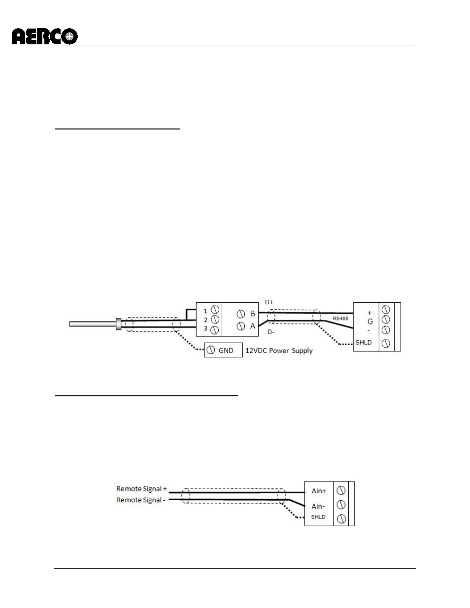
Step 1: Modbus Header Sensor
1. Using Shielded pair 18 - 22 AWG cable, Connect the Temperature Transmitter (AERCO P/N
65169) terminal Pin B to the RS485+ terminal on the I/O Box of any of the boiler units, and
Pin A of the Temperature Transmitter to the RS485- terminal on the I/O Box of any of the
boiler units.
2. Using Shielded pair 18 - 22 AWG cable, connect the Modbus Header Temperature Sensor
(AERCO PN 24410) to pins 2 and 3 of the Temperature Transmitter.
3. Install a jumper wire between pins 1 and 2 of the Temperature Transmitter.
NOTES:
• Polarity must be observed for the RS485 connections. The ground for the shield is at the
“SHLD” terminal in the I/O the Box.
• The header sensor must be installed between 2 and 10 feet downstream of the LAST boiler
in the plant’s supply water header.
• There is no polarity to be observed. The ground for the shield is at the power supply
ground. The sensor end of the shield must be left free and ungrounded.
Step 2: Direct Wired 0-20ma or 4-20ma Wiring
1. Connect the 4-20ma or 0-20ma terminals from the Direct Drive source to the Ain+ and Ain-
terminals on the Master.
NOTES:
• Unit’s I/O Box. Shielded pair 18 - 22 AWG cable is recommended for this connection.
Polarity must be observed.
• The ground for the shield is at the driver signal source.
Temp Sensor PN 24410
Modbus Transmitter
I/O Box
I/O Box