C-more controller for benchmark, innovation & kc – AERCO C-More Controls Manual June 2010 User Manual
Page 114
C-More Controller for Benchmark, Innovation & KC
USER MANUAL
Page 114 of 162
AERCO International, Inc. • 100 Oritani Dr. • Blauvelt, New York 10913
04/22/14
GF-112
Phone: 800-526-0288
OMM-0032_0E
See Section 9.6.3 Step 1 for wiring instructions. In this mode the temperature probe
must be a BALCO 1K type probe.
• Modbus Network
When selecting Network as the Outdoor Temp Source, The Temperature probe is
connected to a Modbus Temperature transmitter as defined in Section 9.6.3, Step 2.
o
When selecting Network as the Head Temp Source, a Modbus Address
(Outdoor Temp Addr) and Modbus Point (Outdoor Temp Point) must be
entered to Define the Modbus Address and Point of the Modbus temperature
transmitter.
BST Remote Signal (Default = 4-20ma / 1-5V)
The BST Remote Signl item will only be displayed if Remote Setpoint Mode is selected. The
unit’s Setpoint can be remotely controlled by an Energy Management System (EMS)
The BST Remote Signl item selections are as follows:
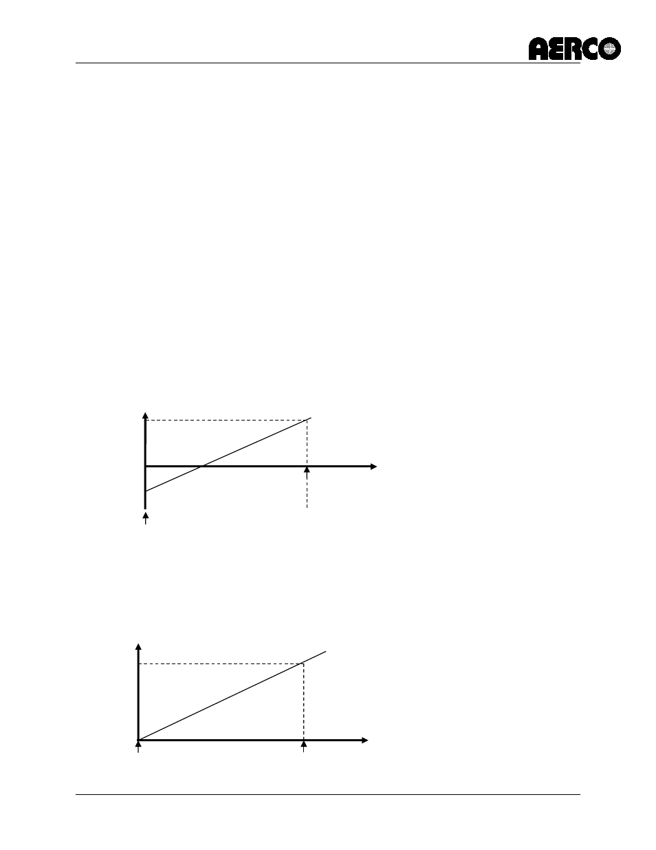
• 4-20ma / 1-5V
When the BST Remote Signl item is set to 4-20ma / 1-5V, a 4 to 20 mA/1 to 5 Vdc
signal, sent by an EMS or BAS, is used to change the unit's setpoint. The 4 mA/1V
signal is equal to the value entered in “BST Setpt Lo Limit” while a 20 mA /5V signal is
equal to the value entered in “BST Setpt Hi Limit”.
• 0-20ma / 0-5V
When the BST Remote Signl item is set to 0 - 20 mA/0 - 5 Vdc, 0 mA is equal to the
value entered in “BST Setpt Lo Limit” while a 20 mA /5V signal is equal to value entered
in “BST Setpt Hi Limit”.
20ma
0ma
4ma
20ma
Remote Setpoint
4-20ma
drive
current
BST Setpt Lo
Limit
BST Setpt Hi Limit
Remote Setpoint
BST Setpt Lo
Limit
BST Setpt Hi Limit
0-20ma
drive
current