AERCO BMK 2000DF User Manual
Page 86
Benchmark 1500DF - 2000DF Boilers
CHAPTER 6 – SAFETY DEVICE TESTING
Page 86 of 196
AERCO International, Inc. • 100 Oritani Dr. • Blauvelt, NY 10913
OMM-0098_0A
04/01/2014
Ph.: 800-526-0288
GF-144
Blocked Inlet Switch
Test – Continued
WARNING
THE BLOWER SUCTION IS VERY STRONG AND CAN PULL NEARBY
OBJECTS INTO THE BLOWER’S FAN BLADES. DO ALLOW ANYTHING
TO BE PULLED INTO THE BLOWER. DO NOT WEAR ANYTHING THAT
COULD GET CAUGHT AND PULL YOU INTO THE BLOWER.
3. Turn off the gas supply ball valve to the boiler and then complete the following steps:
(a) Use jumper wires to jump out the Low Gas Pressure Switch and the Blower Proof
Switch.
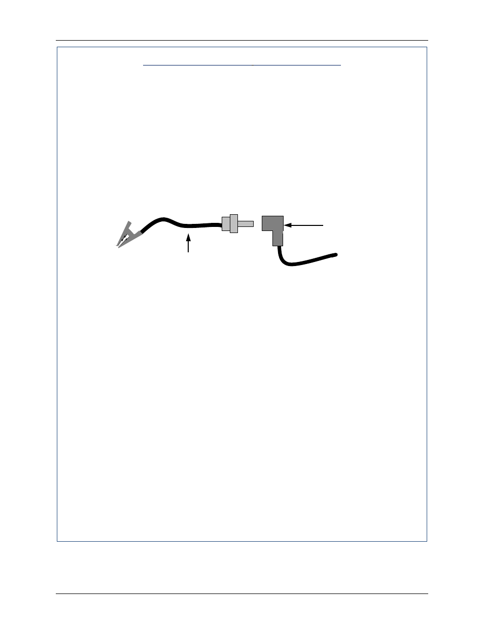
(b) Remove the black connector boot from the Flame Detector.
(c) Connect the Flame Signal Generator to the black connector boot.
Figure 6.3a: Connecting the
Flame Signal Generator
(d) Keep the alligator clip away from bare metal parts until step 3b.
4. Complete the following with the boiler operating in Manual mode:
(a) Ramp the boiler up to 100% fire rate and then turn on the main ON/OFF switch on
the front of the Control Panel.
(b) Push the BACK button three (3) times to return to the upper level menu.
(c) When the Controller gets into the ignition phase, the Control Panel will show
IGNITION TRIAL. At that point attach the alligator clip (see Figure 6.3a) to any bare
metal surface or ground. The C-More display should now show FLAME PROVEN
and begin to ramp up to 100% fire rate. Note that no gas or flame is present in the
boiler at this time.
5. Wait for the boiler to ramp up to at least 90% before continuing.
6. Cover the combustion air inlet opening with a solid, flat object, such as a piece of
plywood or metal plate.
7. The unit should shut down and display AIRFLOW FAULT DURING RUN. This step
confirms proper operation of the Blocked Inlet Switch.
8. Remove the cover from the air inlet opening and reinstall the Combustion Air Duct or air
filter.
9. Remove the jumper wires installed in step 2 and replace the black connector boot on
the Flame Detector.
10. Press the CLEAR button. The unit should restart.
TO WIRE HARNESS
Flame Detector
Connector Boot
Flame Signal Generator