AERCO BMK 2000DF User Manual
Page 57
Benchmark 1500DF - 2000DF Boilers
CHAPTER 4 – INITIAL START-UP
OMM-0098_0A
AERCO International, Inc. • 100 Oritani Dr. • Blauvelt, NY 10913
Page 57 of 196
GF-144
Ph.: 800-526-0288
04/01/2014
NATURAL GAS Combustion Calibration – Continued
13. Compare the oxygen readings on the combustion analyzer to the on-board O
2
sensor
value displayed in the Operating Menu of the C-More Control Panel. If the values differ by
more than ±1.5% and your combustion analyzer is correctly calibrated, the on-board O
2
sensor may be defective and need to be replaced.
14. Compare the measured oxygen level to the oxygen range shown below. Also, ensure that
the nitrogen oxide (NOx) and carbon monoxide (CO) readings do not exceed the values
shown. If you are not in a “NOx-limited” area and/or do not have a NOx measurement in
your analyzer, set the oxygen (O
2
) at 5.5% ± 0.5%.
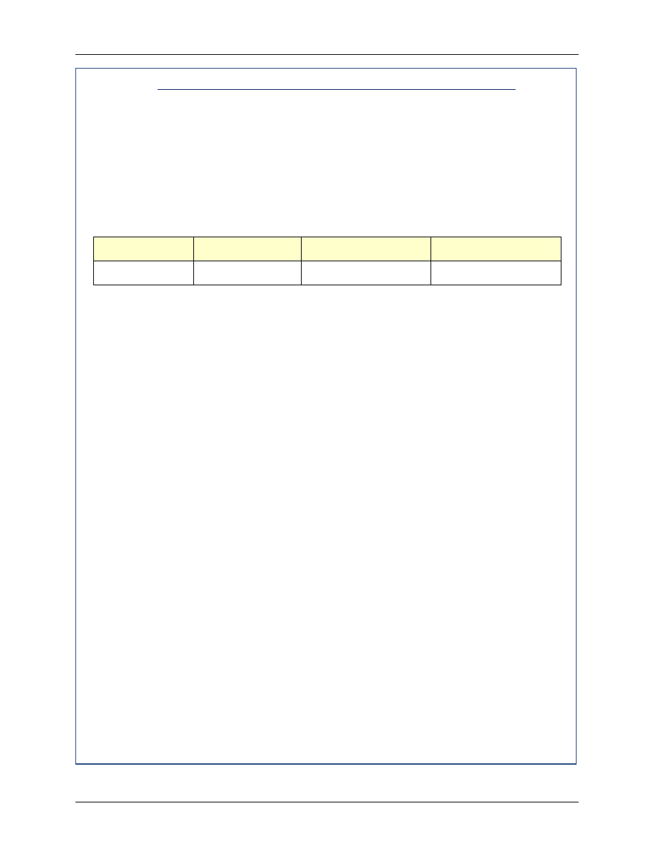
Combustion Calibration Readings – 100% valve Position
Valve Position
Oxygen (O
2
) %
Nitrogen Oxide (NOx)
Carbon Monoxide (CO)
100%
5.0% - 6.0%
≤20 ppm
<100 ppm
15. If the oxygen level is not within the required tolerance, the gas pressure on the
downstream side of the SSOV must be adjusted using the gas pressure adjustment
screw on the SSOV (Figure 4-3). Slowly rotate the gas pressure adjustment
(approximately 1/4-turn increments). Allow the combustion analyzer to stabilize following
each adjustment. Clockwise rotation reduces the oxygen level, while counterclockwise
rotation increases the oxygen level.
16. Once the oxygen level is within the specified range at 100%, record the O
2
, NOx and CO
readings on the Combustion Calibration Data Sheets provided with the unit.
17. Lower the valve position to 80% using the ▼arrow key.
NOTE
The remaining combustion calibration steps are performed using
the Combustion Cal Menu included in the C-More Control System.
The combustion calibration control functions will be used to adjust
the oxygen level (%) at valve positions of 80%, 60%, 45%, 30%
and 16% as described in the following steps. These steps assume
that the inlet air temperature is within the range of 50°F to 100°F.
If NOx readings exceed the target values shown, increase the O
2
level up to 1% higher than the listed calibration range. Record the
increased O
2
value on the Combustion Calibration sheet.
18. Press the MENU key on the front panel of the C-MORE and access the Setup menu.
Enter password 6817 and then press the ENTER key.
19. Press the MENU key on the front panel of the C-MORE until Combustion Cal Menu
appears on the display.
20. Press the ▲ arrow key until SET Valve Position appears on the display.
21. Press the CHANGE key. SET Valve Position will begin to flash.
22. Press the ▲ arrow key until the SET Valve Position reads 80%. Press the ENTER key.
23. Next, press the down (▼) arrow key until CAL Voltage 80% is displayed.
24. Press the CHANGE key and observe that CAL Voltage 80% is flashing.