7 condensate drain & piping – AERCO BMK 2000DF User Manual
Page 20
Benchmark 1500DF - 2000DF Boilers
CHAPTER 2 – INSTALLATION
Page 20 of 196
AERCO International, Inc. • 100 Oritani Dr. • Blauvelt, NY 10913
OMM-0098_0A
04/01/2014
Ph.: 800-526-0288
GF-144
are allowed in the discharge line. In multiple unit installations the discharge lines must not be
manifolded together. Each must be individually run to a suitable discharge location.
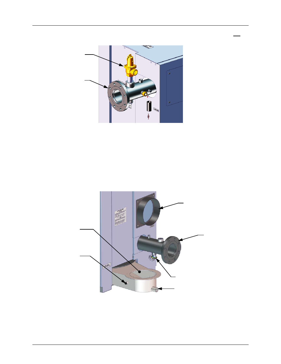
Figure 2-4: P&T Relief Valve Location
2.7 CONDENSATE DRAIN & PIPING
The Benchmark Boiler is designed to condense water vapor from the flue products. Therefore,
the installation must have provisions for suitable condensate drainage or collection.
The condensate drain port located on the exhaust manifold (Figure 2-5) must be connected to
the condensate trap (P/N 24060) which is packed separately within the unit’s shipping container.
The condensate trap inlet features two integral O-rings and a thumbscrew to allow direct
connection of the drain port into the trap inlet. See the Condensate trap Installation instructions
and Figure 2-6 on the next page.
Figure 2-5: Condensate Drain Connection Location
A sample condensate trap installation is shown in Figure 2-6. The following general guidelines
must be observed to ensure proper condensate drainage:
•
The condensate trap inlet (Figure 2-6) must be level the exhaust manifold drain port.
•
The base of the condensate trap must be supported to ensure that it is level (horizontal).
•
The trap must be removable for routine maintenance.
PRESSURE
RELIEF VALVE
4” HOT BOILER
WATER OUTLET
AIR INLET
PRIMARY
WATER INLET
DRAIN VALVE
CONDENSATE DRAIN PORT
1/4” ANALYZER
NPT PORT
EXHAST
MANIFOLD