10 field control wiring – AERCO BMK 2000DF User Manual
Page 26
Benchmark 1500DF - 2000DF Boilers
CHAPTER 2 – INSTALLATION
Page 26 of 196
AERCO International, Inc. • 100 Oritani Dr. • Blauvelt, NY 10913
OMM-0098_0A
04/01/2014
Ph.: 800-526-0288
GF-144
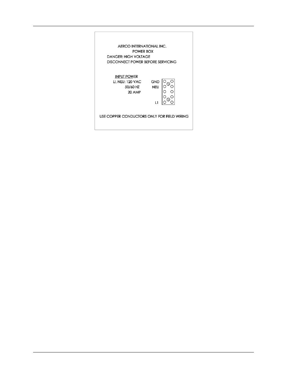
Figure 2-10: Power Box Cover Labels – 120VAC
Each unit must be connected to a dedicated electrical circuit. NO OTHER DEVICES SHOULD
BE ON THE SAME ELECTRICAL CIRCUIT AS THE BOILER.
A three-pole switch must be installed on the electrical supply line in an easily accessible location
to quickly and safely disconnect electrical service. DO NOT attach the switch to sheet metal
enclosures of the unit.
After placing the unit in service, the ignition safety shutoff device must be tested. If an external
electrical power source is used, the installed boiler must be electrically bonded to ground in
accordance with the requirements of the authority having jurisdiction. In the absence of such
requirements, the installation shall conform to National Electrical Code (NEC), ANSI/NFPA 70
and/or the Canadian Electrical Code (CEC) Part I, CSA C22.1 Electrical Code.
For electrical power wiring diagrams, see the AERCO Benchmark Electrical Power Guide, (GF-
2060).
2.10 FIELD CONTROL WIRING
Each unit is fully wired from the factory with an internal operating control system. No field control
wiring is required for normal operation. However, the C-More Control system used with all
Benchmark units does allow for some additional control and monitoring features. Wiring
connections for these features are made on the Input/Output (I/O) board located behind the
removable front panel assembly of the unit. The I/O board is located in the upper-left portion on
the front of the unit as shown in Figure 2-11. The I/O board terminal strip connections are shown
in Figure 2-12. All field wiring is installed from the rear of the panel by routing the wires through
one of the four bushings provided on the sides of the I/O board.
Refer to the wiring diagram provided below the I/O Box (Figure 2-12) when making all wiring
connections.