4 low water level fault test – AERCO BMK 2000DF User Manual
Page 80
Benchmark 1500DF - 2000DF Boilers
CHAPTER 6 – SAFETY DEVICE TESTING
Page 80 of 196
AERCO International, Inc. • 100 Oritani Dr. • Blauvelt, NY 10913
OMM-0098_0A
04/01/2014
Ph.: 800-526-0288
GF-144
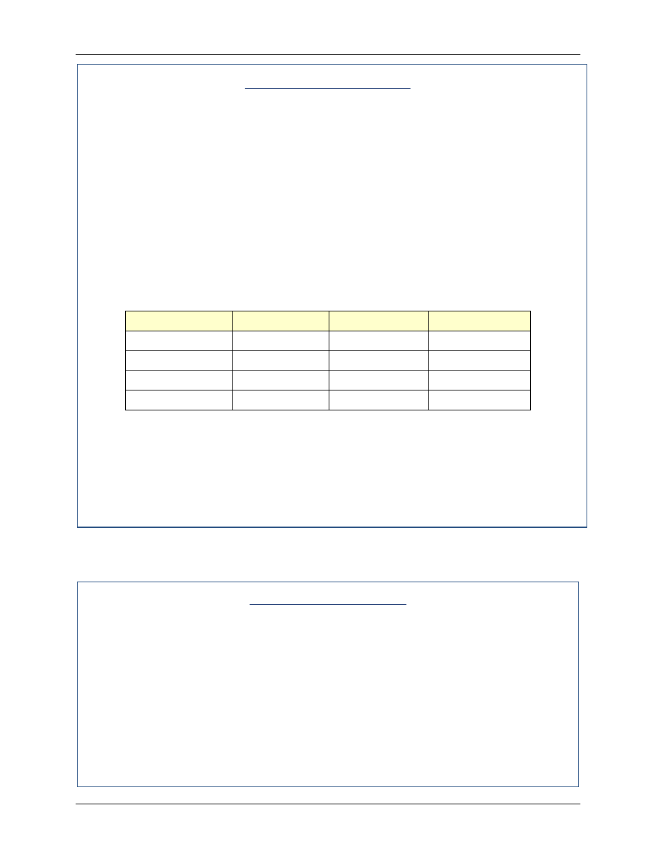
High Gas Pressure Test
1. Ensure that the appropriate high gas pressure leak detection ball valve (Natural Gas or
Propane) is closed (see Figure 6-1b). Note that there are two Natural Gas leak detection
ball valves (for high and low pressure) but only one on the Propane gas train.
2. Remove the 1/4“ plug from the leak detection ball valve shown in Figure 6-1b.
3. Install a 0 – 16” W.C. manometer (or W.C. gauge) where the 1/4” plug was removed.
4. Slowly open the leak detection ball valve.
5. Start the unit in Manual mode at a valve position (firing rate) between 25 and 30%.
6. With the unit running, monitor the gas pressure on the manometer installed in step 2 and
record the gas pressure reading.
7. Slowly increase the gas pressure using the adjustment screw on the SSOV (see Figure
4-3).
8. The unit should shut down and display a HIGH GAS PRESSURE fault message when
the gas pressure exceeds the value in the Gas Pressure column in Table 6-1, below.
Table 6-1: High Gas Pressure Switch Test
Unit
Fuel
SwitchSetting
Gas Pressure
BMK 1500DF
Natural Gas
4.7” W.C.
3.5” W.C.
BMK 1500DF
Propane
3.5” W.C.
1.4” W.C.
BMK 2000DF
Natural Gas
7.5” W.C.
6.3” W.C.
BMK 2000DF
Propane
3.5” W.C.
2.5” W.C.
9. Reduce the gas pressure back to the value recorded in step 6. This pressure should be
within the range of the value in Table 6-1, above.
10. Press the CLEAR button on the Control Box to clear the fault.
11. The fault message should clear and the FAULT indicator should go off. The unit should
restart.
12. Upon test completion, close the ball valve and remove the manometer. Replace the 1/4“
plug removed in step 1.
6.4 LOW WATER LEVEL FAULT TEST
To simulate a low water level fault, proceed as follows:
Low Water Level Fault
1. Set the ON/OFF switch to the OFF position
2. Close the water shut-off valves in the supply and return piping to the unit.
3. Slowly open the drain valve on the rear of the unit. If necessary the unit’s relief valve
may be opened to aid in draining.
4. Continue draining the unit until a LOW WATER LEVEL fault message is displayed and
the FAULT indicator flashes.
5. Place the unit in the Manual Mode and raise the valve position above 30%.
6. Set the ON/OFF switch to the ON position. The READY light should remain off and the
unit should not start. If the unit does start, shut the unit off immediately and refer fault to
qualified service personnel.