AERCO BMK 2000DF User Manual
Page 58
Benchmark 1500DF - 2000DF Boilers
CHAPTER 4 – INITIAL START-UP
Page 58 of 196
AERCO International, Inc. • 100 Oritani Dr. • Blauvelt, NY 10913
OMM-0098_0A
04/01/2014
Ph.: 800-526-0288
GF-144
NATURAL GAS Combustion Calibration – Continued
25. The oxygen level at the 80% valve position should be as shown below. Also, ensure that
the nitrogen oxide (NOx) and carbon monoxide (CO) readings do not exceed the
following values:
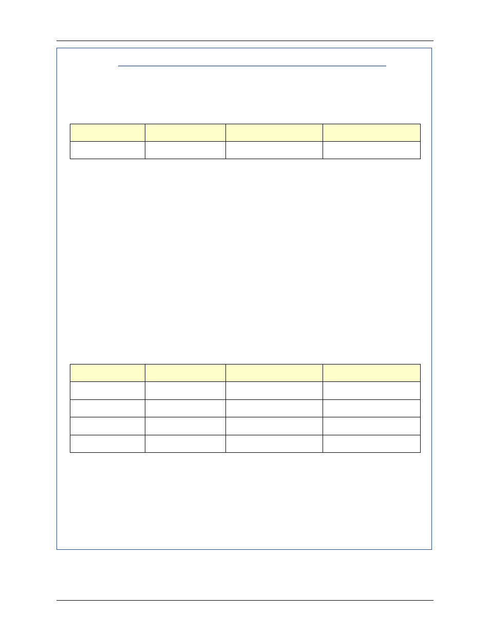
Combustion Calibration Readings – 80% valve Position
Valve Position
Oxygen (O
2
) %
Nitrogen Oxide (NOx)
Carbon Monoxide (CO)
80%
5.4% ± 0.5%
≤50 ppm
<150 ppm
26. If the oxygen level is not within the specified range, adjust the level using the ▲ and ▼
arrow keys. This will adjust the output voltage to the blower motor as indicated on the
display. Pressing the ▲ arrow key increases the oxygen level and pressing the down ▼
arrow key decreases the oxygen level.
27. Once the oxygen level is within the specified range at 80%, press the ENTER key to
store the selected blower output voltage for the 80% valve position. Record all readings
on the Combustion Calibration Sheets provided.
28. Repeat steps 20 through 27 for valve positions of 60%, 45%, 30% and 16%. The oxygen
(O
2
), nitrogen oxide (NOx) and carbon monoxide (CO) should remain within the same
limits for all valve positions as shown in the following table.
NOTE
If NOx readings exceed the target values shown (<20 ppm),
increase the O
2
level up to 1% higher than the listed calibration
range shown in the table. Record the increased O
2
value on the
Combustion Calibration sheet.
Combustion Calibration Readings
Valve Position
Oxygen (O
2
) %
Nitrogen Oxide (NOx)
Carbon Monoxide (CO)
60%
6.0% ± 0.5
<20 ppm
<100 ppm
45%
6.3% ± 0.5
<20 ppm
<100 ppm
30%
6.3% ± 0.5
<20 ppm
<100 ppm
16%
6.0% ± 0.5
<20 ppm
<100 ppm
29. If the oxygen level at the 16% valve position is too high and the Blower voltage is at the
minimum value, you can adjust the idle screw (TAC valve) which is recessed in the top of
the Air/Fuel Valve (see Figure 4-4). Rotate the screw 1/2 turn clockwise (CW) to add fuel
and reduce the O
2
to the specified level. Recalibration MUST be performed again from
60% down to 16% after making a change to the idle screw (TAC valve).
30. This completes the NATURAL GAS combustion calibration procedures.