5 supply and return piping, 6 pressure relief valve installation – AERCO BMK 2000DF User Manual
Page 19
Benchmark 1500DF - 2000DF Boilers
CHAPTER 2 – INSTALLATION
OMM-0098_0A
AERCO International, Inc. • 100 Oritani Dr. • Blauvelt, NY 10913
Page 19 of 196
GF-144
Ph.: 800-526-0288
04/01/2014
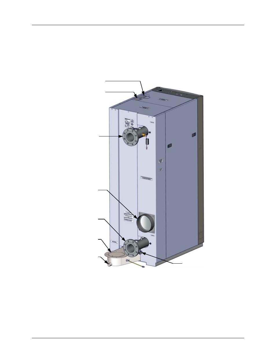
2.5 SUPPLY AND RETURN PIPING
The Benchmark Boiler utilizes 4” 150# flanges for the water system supply and return piping
connections. The physical location of the supply and return piping connections are on the rear of
the unit as shown in Figure 2-3.
Figure 2-3: Supply and Return Locations
2.6 PRESSURE RELIEF VALVE INSTALLATION
An ASME rated Pressure Relief Valve is supplied with each Benchmark Boiler. The pressure
rating for the relief valve must be specified on the sales order. Available pressure ratings range
from 30 psi to 160 psi. The relief valve is installed on the hot water outlet of the boiler as shown
in Figure 2-4. A suitable pipe joint compound should be used on the threaded connections. Any
excess should be wiped off to avoid getting any joint compound into the valve body. The relief
valve must be piped to within 12 inches of the floor to prevent injury in the event of a discharge.
2” NATURAL GAS INLET
BOILER HOT
WATER OUTLET
(SUPPLY)
EXHAUST
MANIFOLD
CONDENSATE
DRAIN PORT
AIR INLET
PRIMARY
WATER INLET
(RETURN)
DRAIN VALVE
1” PROPANE INLET