AERCO BMK 2000DF User Manual
Page 106
Benchmark 1500DF - 2000DF Boilers
CHAPTER 8 – TROUBLESHOOTING GUIDE
Page 106 of 196
AERCO International, Inc. • 100 Oritani Dr. • Blauvelt, NY 10913
OMM-0098_0A
04/01/2014
Ph.: 800-526-0288
GF-144
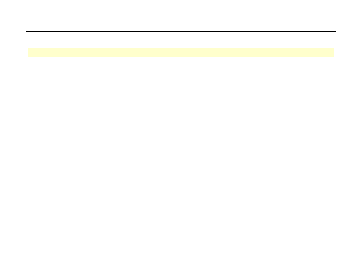
TABLE 8-1: BOILER TROUBLESHOOTING – Continued
FAULT INDICATION
PROBABLE CAUSES
CORRECTIVE ACTION
AIRFLOW FAULT
DURING PURGE
1.
Blower not running or running too
slow.
2.
Defective Blocked Inlet switch.
3.
Blockage in air filter or Blocked
Inlet switch.
4.
Blocked blower inlet or inlet
ductwork.
5.
No voltage to Blocked Inlet switch
from C-More Control Box.
6.
PROBABLE CAUSES from 3 to 12
for AIRFLOW FAULT DURING
IGNITION apply for this fault.
1.
Start the unit. If the blower does not run check the blower solid
state relay for input and output voltage. If the relay is OK, check
the blower.
2.
Start the unit. If the blower runs, turn off unit and check the
Blocked Inlet switch for continuity. Replace the switch if
continuity does not exist.
3.
Remove the air filter and Blocked Inlet switch and inspect for
signs of blockage. Clean or replace as necessary.
4.
Inspect the inlet to the combustion blower including any
ductwork leading up to the combustion blower for signs of
blockage.
5.
During the start sequence, verify that 24 VAC is present
between each side of the switch and ground. If 24 VAC is not
present, refer fault to qualified service personnel.
6.
See CORRECTIVE ACTIONS from 3 to 12 for AIRFLOW
FAULT DURING IGNITION.
AIRFLOW FAULT
DURING RUN
1.
Blower stopped running due to
thermal or current overload.
2.
Blocked Blower inlet or inlet
ductwork.
3.
Blockage in air filter or Blocked
Inlet switch.
4.
Defective Blocked Inlet switch.
5.
Combustion oscillations.
6.
Probable causes from 3 to 16 for
AIRFLOW FAULT DURING
IGNITION applies for this fault.
1.
Check combustion blower for signs of excessive heat or high
current draw that may trip thermal or current overload devices.
2.
Inspect the inlet to the combustion blower, including any
ductwork leading up to the combustion blower, for signs of
blockage.
3.
Remove the air filter and Blocked Inlet switch and inspect for
signs of blockage, clean or replace as necessary.
4.
Verify that 24 VAC is present between each side of the switch
and ground. If 24 VAC is not present at both sides, replace
switch.
5.
Run unit to full fire. If the unit rumbles or runs rough, perform
combustion calibration.
6.
See CORRECTIVE ACTIONS from 3 to 12 for AIRFLOW
FAULT DURING IGNITION.