AERCO BMK 2000DF User Manual
Page 21
Benchmark 1500DF - 2000DF Boilers
CHAPTER 2 – INSTALLATION
OMM-0098_0A
AERCO International, Inc. • 100 Oritani Dr. • Blauvelt, NY 10913
Page 21 of 196
GF-144
Ph.: 800-526-0288
04/01/2014
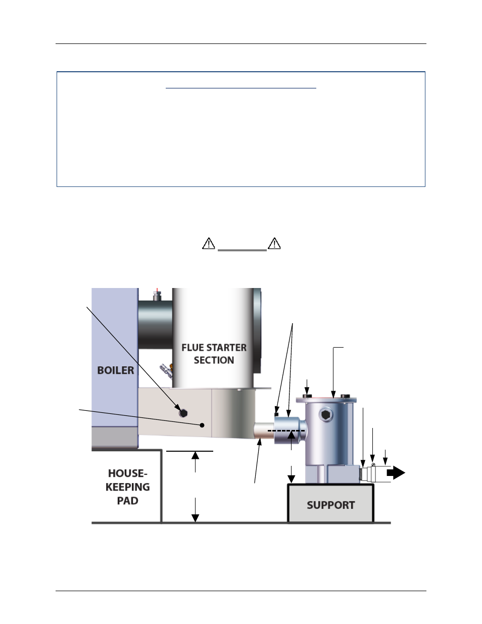
While observing the above guidelines, install the condensate trap as follows:
Condensate Trap Installation
1. Connect the condensate trap inlet to the exhaust manifold drain connection by inserting
the drain port directly into the trap adaptor inlet, and then tightening the inlet thumbscrew,
as shown in Figure 2-6. The inlet features two integral O-rings to prevent leakage.
2. At the condensate trap outlet, install a 3/4” NPT nipple.
3. Connect a length of 1” diameter polypropylene hose to the trap outlet and secure with a
hose clamp.
4. Route the hose on the trap outlet to a nearby floor drain.
If a floor drain is not available, a condensate pump can be used to remove the condensate to
drain. The maximum condensate flow rate is 30 GPH. The condensate drain trap, associated
fittings and drain line must be removable for routine maintenance.
Use PVC, stainless steel, aluminum or polypropylene for condensate drain
piping (Figure 2-6). DO NOT use carbon or copper components.
Figure 2-6: Sample Condensate Trap Installation (Right Side View)
CAUTION
EXHAUST
MANIFOLD
DRAIN PORT
COMBUTION
ANALYZER
PROBE PORT
EXHAUST
MANIFOLD
3/4” NPT
NIPPLES
HOSE
CLAMP
T O
FLOOR
DRAIN
CONDENSATE
TRAP (P/N 24060)
TRAP INLET
INTEGRAL
ADAPTOR AND
THUMBSCREW
TOP
COVER
THUMB
SREWS
(4 ea.)
1” DIAM.
HOSE
NOTE
HOUSKEEPING
PAD MUST NOT
EXTEND
UNDER THE
CONDENSATE
ASSEMBLY.
4” MINIMUM
(8” MAXIMUM)
4”