Circuit diagrams, Cable type input/output circuit diagram, M8 connector type input/output circuit diagram – KEYENCE LV-N10 Series User Manual
Page 93: Monitor output type input/output circuit diagram, Circuit diagrams -5, Lv-n11mn, Sp eci fic at io ns, Digital laser sensor lv-n10 series user's manual
5
Sp
eci
fic
at
io
ns
5-5
- Digital Laser Sensor LV-N10 Series User's Manual -
5-2
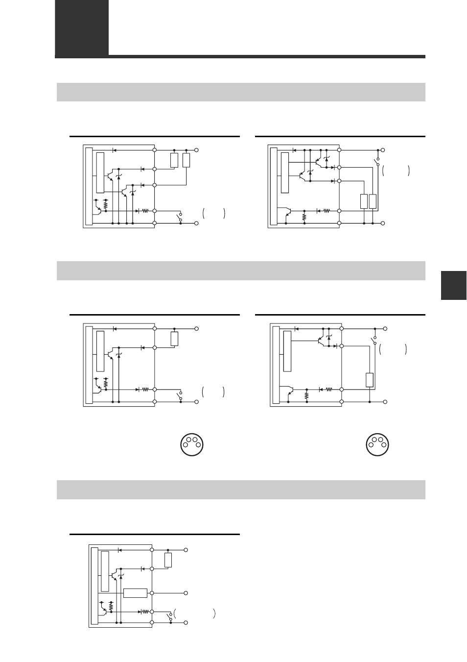
Circuit Diagrams
Cable Type Input/output Circuit Diagram
LV-N11N / N12N
LV-N11P / N12P
*1 LV-N11N only
*1 LV-N11P only
DC10-30V
DC3.3V
Black
(Control output 1)
PLC, etc.
Short-circuit current
1 mA or less
White
(Control output 2)
Pink
Brown
*1
Blue
*1
0V
Sensor main circuit
Ov
ercurrent protection circuit
Load
Load
DC10-30V
Black
(Control output 1)
PLC, etc.
Short-circuit current
2 mA or less
White
(Control
output 2)
Pink
Brown
*1
Blue
*1
0V
Sensor main circuit
Ov
ercurrent protection circuit
Load
Load
M8 Connector Type Input/output Circuit Diagram
LV-N11CN / N12CN
LV-N11CP / N12CP
*1 LV-N11CN only
*1 LV-N11CP only
DC10-30V
DC3.3V
(4)
(Control output)
PLC, etc.
Short-circuit current
1 mA or less
(2)
(1)
*1
(3)
*1
0V
Sensor main circuit
Ov
ercurrent protection circuit
Load
DC10-30V
(4)
(Control output)
PLC, etc.
Short-circuit current
2 mA or less
(2)
(1)
*1
(3)
*1
0V
Sensor main circuit
Ov
ercurrent protection circuit
Load
1
2
3
4
M8 connector pin layout
1
2
3
4
M8 connector pin layout
Monitor Output Type Input/output Circuit Diagram
LV-N11MN
10 to 30 VDC
Device
Impedance:10 k
Ω or more
3.3 VDC
Black (Control output 1)
PLC, etc.
Short-circuit current
1 mA or less
Orange (Monitor output 1 to 5 V)
0 V
Protection circuit
Sensor main circuit
Ov
ercurrent protection circuit
Load
Pink
Blue
Brown