KEYENCE LV-N10 Series User Manual
Page 72
4-4 Display Settings (diSP)
4
Set
tings
for Ad
van
c
ed Fu
nct
ion
s
4-24
- Digital Laser Sensor LV-N10 Series User's Manual -
Excess gain (%) display
Received light intensity is displayed as an excess
gain* relative to the setting value. On the screen,
the received light intensity is displayed as a bar
graph and a percentage number.
* Excess gain = (Received light intensity/Setting
value) x 100
Light intensity hold display
The maximum peak values, and the minimum bottom values, of received light intensity
can be displayed continuously. You can select from 5 possible display combinations:
How to reset the held values
To reset the peak and/or bottom values that are currently held, use one of the following
procedures:
• Press and hold the [MODE] and [SET] buttons simultaneously.
• Set the external input (in) to "reset input (rSt)" and short-circuit the pink wire (pin
(2)).
• Turn off the power.
Refer to page 4-2 "Display Settings (diSP)" for setting methods.
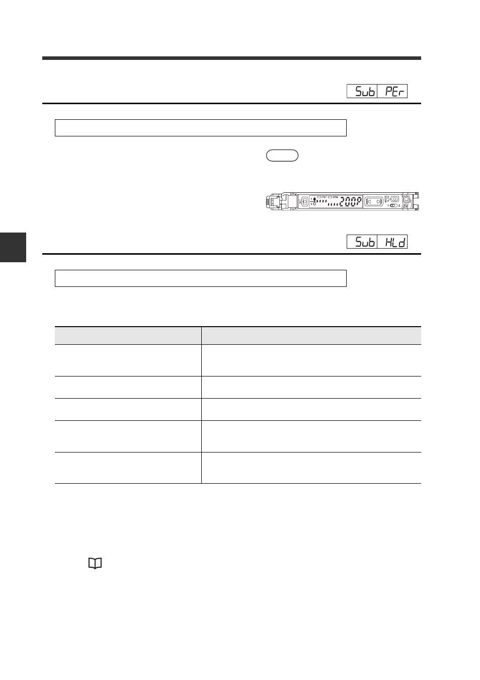
Display example
If the setting value is 1000
and the received light
intensity is 2000 (200%):
Refer to page 4-2 "Display Settings (diSP)" for setting methods.
Display
Displayed values
Std (Standard)
Updates the peak or bottom value each time the cur-
rent received light intensity falls below or rises above,
respectively, the setting value. (Default)
P~P_ (Peak Max/Peak Min)
Displays the maximum and minimum of peak values
since the power is turned on. (Cumulative)
b~b_ (Bottom Max/Bottom Min)
Displays the maximum and minimum of bottom val-
ues since the power is turned on. (Cumulative)
P_b~ (Peak Min/Bottom Max)
Displays the minimum of peak values and the maxi-
mum of bottom values since the power is turned on.
(Cumulative)
P~b_ (Peak Max/Bottom Min)
Displays the maximum of peak values and the mini-
mum of bottom values since the power is turned on.
(Cumulative)