Lv-s41/s41l, Lv-s62, Lv-s41/s41l -8 lv-s62 -8 – KEYENCE LV-N10 Series User Manual
Page 22
2-3 Mounting and Adjusting the Sensor Head
2
In
st
al
la
tio
n
a
nd
Co
nnec
ti
on
2-8
- Digital Laser Sensor LV-N10 Series User's Manual -
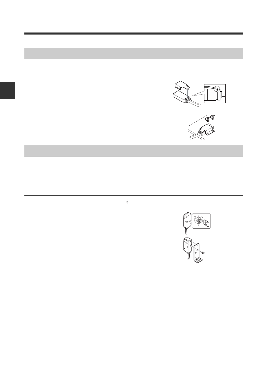
Always use the included mounting bracket.
1
Attach the mounting bracket as shown on
the right.
Match section A of the fitting onto section
B of the sensor head
2
Attach onto a flat surface with M3 screws as
shown on the right.
(M3 screws are not included.)
Mount with the optional L-mounting bracket (OP-84350), back surface mounting
bracket (OP-84349) or horizontal mounting bracket (OP-84351).
L-mounting bracket (optional: OP-84350)
Included: Mounting bracket ×1 / plate nut × 1 / M3 × 7.3 screw × 1
1
Insert the plate nut into the mounting slot on the
back of the head.
2
Align the protrusion with the hole on the top of
bracket, and attach with the included mounting
screws.
LV-S41/S41L
A
B
LV-S62
The tightening
torque is
0.5 N
·m or less.
- LR-TB2000 Series (12 pages)
- LR-TB5000 Series (12 pages)
- LR-ZB250AN/AP (4 pages)
- LR-ZB250AN/P (3 pages)
- LR-ZBxN/P Series (3 pages)
- LR-ZBxxB (3 pages)
- OP-85135 (1 page)
- PZ-G Series (2 pages)
- PZ-V/M (2 pages)
- PS-N10 Series (12 pages)
- PX-10 (10 pages)
- CZ-V21A(P) (10 pages)
- CZ-K1(P) (8 pages)
- CZ-V1 (8 pages)
- FS-N10 Series (6 pages)
- FS-N10 Series (116 pages)
- FS-N15CN (1 page)
- FU-93(Z) (2 pages)
- FU-V Series (2 pages)
- FS-V30 (6 pages)
- FU-A40 (1 page)
- NU/FS-N Series (16 pages)
- FS-V33(P) (8 pages)
- FS-V21 (4 pages)
- FS-V22 (4 pages)
- FS-V11(P) (4 pages)
- FS-V1(P) (4 pages)
- LV-N10 Series (12 pages)
- LV-S62 (1 page)
- OP-84350 (1 page)
- LV-SA (10 pages)
- LV-SB (12 pages)
- OP-87305 (1 page)
- LV Series (10 pages)
- LV-B102 (1 page)
- EV-108M(U) (1 page)
- EZ Series (1 page)
- EM Series (1 page)
- ES-M1(P) (3 pages)
- EX-V Series (120 pages)
- EX-500(W) Series (16 pages)
- GV Series (10 pages)
- IA Series (8 pages)
- LB-1000(W) (24 pages)