Wiring diagrams for sensor amplifiers, Wiring diagrams for sensor amplifiers -4, 1 installing sensor amplifiers – KEYENCE LV-N10 Series User Manual
Page 18
2-1 Installing Sensor Amplifiers
2
In
st
al
la
tio
n
a
nd
Co
nnec
ti
on
2-4
- Digital Laser Sensor LV-N10 Series User's Manual -
• Be sure to turn off the power before wiring.
• Insulate each input or output cable that will not be used.
Refer to
"Circuit Diagrams" (page 5-5) for the input/output circuit
diagrams.
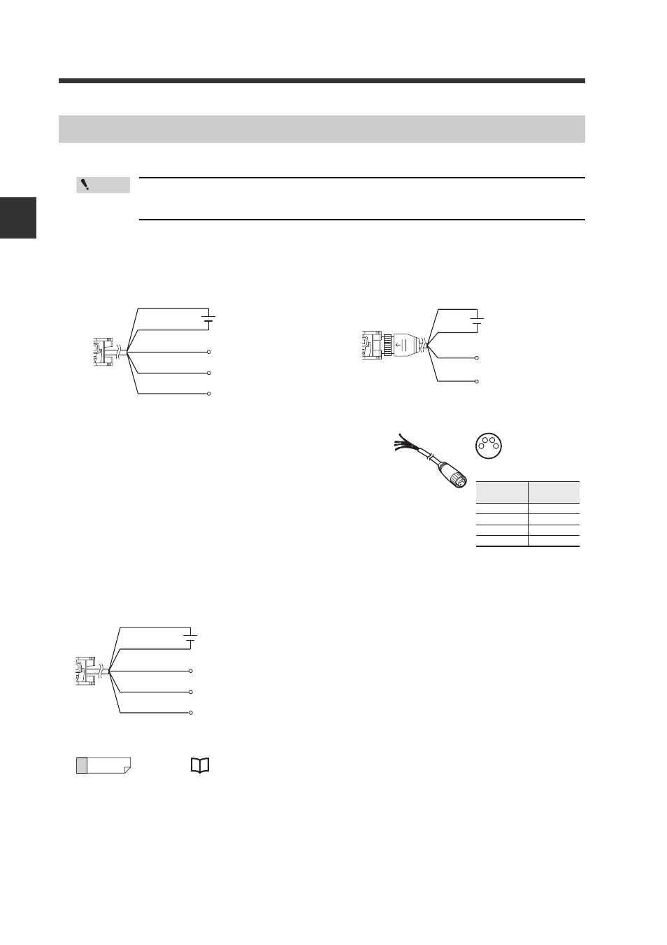
Wiring Diagrams for Sensor Amplifiers
Point
Cable type (LV-N11 /N12 )
M8 connector type (LV-N11C /N12C )
Monitor output type (LV-N11MN)
Brown*
Blue*
Black
10 to 30 VDC
* LV-N11N/N11P only
Output 1
External input
Output 2
White
Pink
(1)*
(3)*
10 to 30 VDC
* LV-N11CN/N11CP only
(4)
External input
Output
(2)
OP-73864
(Cable length: 2 m)
OP-73865
(Cable length: 10 m)
1
2
3
4
Connected
pin No.
Pin and wire color table
1
Brown
2
3
4
White
Blue
Black
Wire color
Brown
Blue
Black
10 to 30 VDC
*Connect to a device having an input impedance of 10k
Ω
or more.
Output
External input
Monitor output (1 to 5 V)
Orange*
Pink
Reference