KEYENCE LV-N10 Series User Manual
Page 23
2-3 Mounting and Adjusting the Sensor Head
2
In
st
al
la
tio
n
a
nd
Co
nnec
ti
on
2-9
- Digital Laser Sensor LV-N10 Series User's Manual -
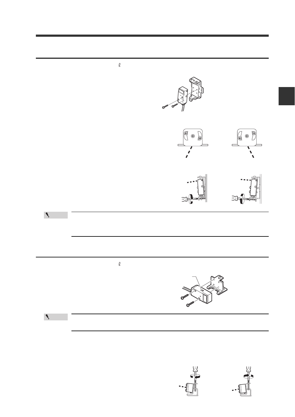
Back surface mounting bracket (optional: OP-84349)
Included: Mounting bracket × 1 / M3 × 18 screw × 2
1
Attach as shown on the right.
2
Adjust the beam axis.
(1) The beam axis angle can be adjusted side-
ways by loosening screws (a), (b), and (c)
and moving the bracket left and right. Always
tighten screw (b) first.
(2) The beam axis can be adjusted in the
downward direction by tightening the bot-
tom screw as shown with the arrow. It can
be adjusted in the upward direction by loos-
ening the same screw.
Always adjust the beam axis in the order of steps (1) and (2).
The screws shown in (1) could be damaged if these steps are
reversed.
Horizontal mounting bracket (optional: OP-84351)
Included: Mounting bracket × 1 / M3 × 18 screw × 2
1
Attach as shown on the right.
When mounting the sensor head in the direction opposite of that
shown above, set the spot selection switch before mounting.
2
Adjust the beam axis.
The beam axis can be adjusted in the
upward direction by tightening the
screw as shown with the arrow. It can
be adjusted in the downward direction
by loosening the same screw.
The tightening torque is
0.5 N
·m or less.
(c)
(c)
To move the beam axis
downward
To move the beam axis
upward
Point
Spot selection
switch
The tightening torque is
0.5 N
·m or less.
Point
To move the beam axis
upward
To move the beam axis
downward