Lv-s71/s72, Lv-s71/s72 -10 – KEYENCE LV-N10 Series User Manual
Page 24
2-3 Mounting and Adjusting the Sensor Head
2
In
st
al
la
tio
n
a
nd
Co
nnec
ti
on
2-10
- Digital Laser Sensor LV-N10 Series User's Manual -
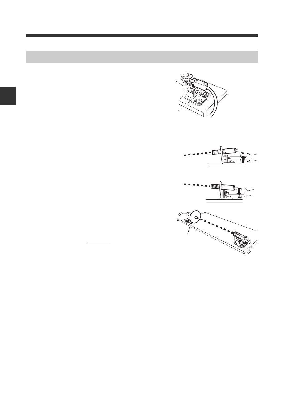
1
Attach so that the side on which
the T (transmitter) and R (receiver)
are printed faces upward. The
operation indicator lights are on
the printed side.
2
Adjust the beam axis.
The beam axis can be adjusted in the downward
direction by tightening the screw as shown with
the arrow. It can be adjusted in the upward direc-
tion by loosening the same screw.
Adjust so that the beam spot is centered on
the receiver.
When adjusting, attach the beam axis align-
ment plate, included with the sensor head, onto
the end of the receiver to aid in alignment.
Remove the beam axis alignment plate cap
when finished adjusting.
LV-S71/S72
Fixing nut
Axis beam
adjustment screw
The tightening torque is
1.2 N·m or less.
To move the beam axis downward
To move the beam axis upward
Beam axis
alignment
plate
- LR-TB2000 Series (12 pages)
- LR-TB5000 Series (12 pages)
- LR-ZB250AN/AP (4 pages)
- LR-ZB250AN/P (3 pages)
- LR-ZBxN/P Series (3 pages)
- LR-ZBxxB (3 pages)
- OP-85135 (1 page)
- PZ-G Series (2 pages)
- PZ-V/M (2 pages)
- PS-N10 Series (12 pages)
- PX-10 (10 pages)
- CZ-V21A(P) (10 pages)
- CZ-K1(P) (8 pages)
- CZ-V1 (8 pages)
- FS-N10 Series (6 pages)
- FS-N10 Series (116 pages)
- FS-N15CN (1 page)
- FU-93(Z) (2 pages)
- FU-V Series (2 pages)
- FS-V30 (6 pages)
- FU-A40 (1 page)
- NU/FS-N Series (16 pages)
- FS-V33(P) (8 pages)
- FS-V21 (4 pages)
- FS-V22 (4 pages)
- FS-V11(P) (4 pages)
- FS-V1(P) (4 pages)
- LV-N10 Series (12 pages)
- LV-S62 (1 page)
- OP-84350 (1 page)
- LV-SA (10 pages)
- LV-SB (12 pages)
- OP-87305 (1 page)
- LV Series (10 pages)
- LV-B102 (1 page)
- EV-108M(U) (1 page)
- EZ Series (1 page)
- EM Series (1 page)
- ES-M1(P) (3 pages)
- EX-V Series (120 pages)
- EX-500(W) Series (16 pages)
- GV Series (10 pages)
- IA Series (8 pages)
- LB-1000(W) (24 pages)