KEYENCE LV-N10 Series User Manual
Page 13
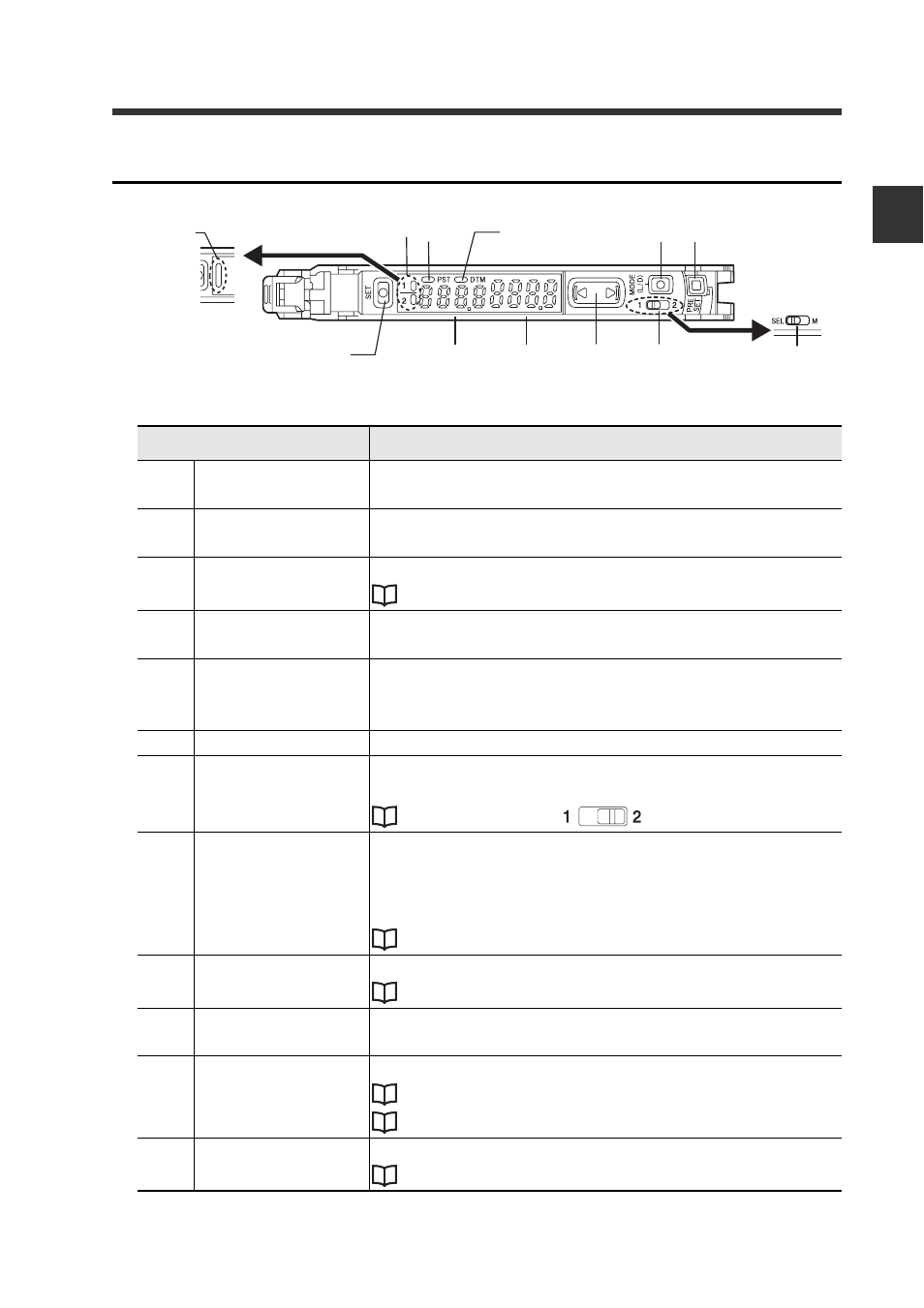
1-2 Part Names
1
Bef
o
re
U
s
in
g
1-5
- Digital Laser Sensor LV-N10 Series User's Manual -
Display/control unit
* Not available for the LV-N10.
Item
Description
(1)-1
Operation indicator
(2-output type)
Indicates the current output (detection) status of chan-
nels 1 and 2 separately.
(1)-2
Operation indicator
(1-output type)
Indicates the current output (detection) status.
(2)
[SET] button
Used when setting sensitivity, etc.
"Adjusting the Sensitivity" (page 3-5)
(3)
Setting value
(Displayed in green)
Displays a setting value or advanced setting item in this
area of 7-segment green indicators.
(4)
Current value
(Displayed in red)
Displays the current value (received light intensity), or a
selection from advanced settings, in this area of 7-seg-
ment red indicators.
(5)
Manual button
Used to adjust the setting value or select an option.
(6)-1
Channel select
switch
(2-output type)
Toggles between channels 1 and 2 for configuring the
received light intensity display or sensitivity setting.
"2-output Settings (
(6)-2
Power select switch
(1-output type)
Changes power modes.
SEL: Allows you to set a power mode using the "Chang-
ing Power Modes" function of basic setup.
M:
Fixes the power mode to "MEGA mode".
"Locking in MEGA Mode" (page 3-22)
(7)
[PRESET] button
Used for presetting or setting values or parameters.
"Adjusting the Sensitivity" (page 3-5)
(8)
[MODE] button
Used for toggling L-on/D-on, proceeding to advanced
settings, or confirming selections.
(9)
DTM indicator
Lights when a DATUM mode is in effect.
(10) PST indicator
Lights when preset value is set.
"Adjusting the Sensitivity" (page 3-5)
(3)
(4)
(5)
(8)
(6)-1
*
(7)
(2)
(1)-1
(9)
(10)
(1)-2
(6)-2
*