Lv-s31, Lv-s31 -7 – KEYENCE LV-N10 Series User Manual
Page 21
2-3 Mounting and Adjusting the Sensor Head
2
In
st
al
la
tio
n
a
nd
Co
nnec
ti
on
2-7
- Digital Laser Sensor LV-N10 Series User's Manual -
2
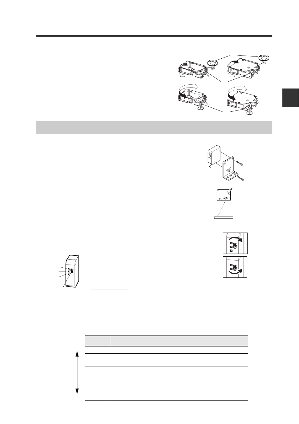
Adjust the beam axis.
(1) Adjust the beam axis upward by tightening the
(a) screw, and downward by loosening the
screw. Fix the angle setting with the (b) nut.
(2) Adjust the horizontal angle by loosening the
fixing section (c).
1
Mount using the Included mounting
bracket.
2
Place a workpiece at the position to be
set as the detection center.
3
Turn the trimmer with the Included adjustment
screwdriver, and adjust so that the (2) JUS indi-
cator lights in green.
When the LV-S31 is connected, the workpiece position is numerically displayed on the
main screen (red display) using the center position as [5000]. If adjust the workpiece
position precisely, set the display of sensor amplifier approximate [5000]. The display
changes as follows according to the workpiece position.
(a)
(b)
(c)
LV-S31
Display
Meaning
----
Out of detection range
nEAr
The detector is nearer to the sensor side than numerical dis-
play range
5000
Centering on 5000, the value increases as the workpiece dis-
tance increases from the sensor
FAr
The workpiece is farther from the sensor than the numerical
display range
----
Out of detection range
F
F
N
J
N
F
J
N
F
N
F
J
N
F
N
F
J
N
F
N
(1)
(2)
(3)
Trimmer
Near
Far
If the (1) FAR indicator is ON, turn the trimmer
clockwise until (2) turns ON.
If the (3) NEAR indicator is ON, turn the trimmer
counterclockwise until (2) turns ON.