I dip switch setting on the control site, Pc connection, Connection to a client pc via hub – Panasonic WV-CU20 User Manual
Page 32: Dido
Attention! The text in this document has been recognized automatically. To view the original document, you can use the "Original mode".
i DIP Switch Setting on the Control Site
1. Set the WJ-NT204 Rear DIP Switch as follows. This set
ting applies when connecting with PS’Data devices
such as System Controller on the Control site.
Bit # 1 : ON/OFF
Bit #2: ON/OFF
Bit#3: OFF
Bit #4: OFF
Bit #5: ON/OFF
Bit #6: ON/OFF
Termination, set to ON at the
end of the RS-485 DATA line,
wise OFF,
Termination, set to ON at the
end of the RS-485 DATA line,
wise OFF.
Straight wiring for RS-485
PORT
RS-485 DATA port is selected.
Termination, set to ON at the
end of the RS-485 HOST line,
wise OFF.
Termination, set to ON at the
end of the RS-485 HOST line,
wise OFF.
chain
other-
chain
other-
DATA
chain
other-
chain
other-
ON
OFF
dido
ddd
WJ-NT204 (Receiver)
SETUP DIP Switch
2 3 4 5 6
L OFF: RS-485 DATA PORT selected
— OFF: Straight wiring for RS-485 DATA PORT
— ON, ON: Termination for DATA Lines
— OFF, OFF: Open for DATA Line
2. Set the DIP Switch and Unit Number Switch on the rear
of the System Controller WV-CU360 as follows. For
details refer to the manual included in the System
Controller.
DIP Bit #5:
ON/OFF
Unit Number: Setto 1.
Termination for RS-485
(PS-DATA), set to ON at the
RS-485 chain end, otherwise
set to OFF.
OFF
□ □ □ □
u u u
□
System Controller
WV-CU360
1 2 3 4 5 6 7 8
— Set the unit number
— ON: Termination for
RS-485 (PS-Data) Lines
— OFF: Open for Lines
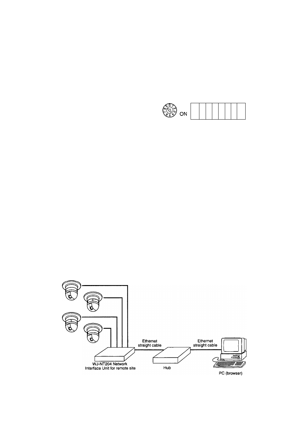
■ PC Connection
Connect the Remote site unit to the PC via a hub with Ethernet straight cables as shown below,
For more details, refer to LAN TYPE CONNECTION on page 66.
Connection to a Client PC via Hub
Combination Cameras (4)
32