Address setup, Communication parameter setup, Input assignment – Panasonic WV-CU20 User Manual
Page 121: Wj-hd500 digital disk recorder control (coax)
Attention! The text in this document has been recognized automatically. To view the original document, you can use the "Original mode".
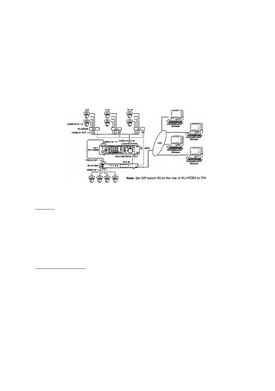
This is a system example that the WJ-NT204 transmitter has 4 of directly connected combination cameras while it has 12 of
combination cameras connected indirectly via the WJ-MP204 and WJ-HD500.
• Connections
1. Connect 4 combination cameras to VIDEO IN 1-4 on the \A/J-NT204 with coaxial cables,
2. Connect VIDEO OUT 1-4 on the WJ-NT204 to VIDEO IN 1-4 on the WJ-HD500.
3. Connect MULTISCREEN OUT on the rear of the WJ-HD500 to VIDEO AUX IN on the WJ-NT204 with a BNC attached coax
ial cable.
4. Connect 12 combination cameras to CAMERA IN 1-4 on WJ-MP204 unit #1 through #3 with coaxial cables,
5. Connect CAMERA OUT 1-4 on WJ-MP204 unit #1 through #3 to VIDEO IN 5-16 on the WJ-HD500.
6. Connect DATA terminals among WJ-MP204, WJ-HD500 and WJ-NT204 with RS-485 cables and branch connectors.
■ WJ-HD500 Digital Disk Recorder Control (Coax)
Combination Camera 5-16
t Setup for Peripheral Devices
1. Address Setup
Unit addresses must be set as follow.
Unit Name
WJ-HD500
WJ-MP204 #1
WJ-MP204 #2
WJ-MP204 #3
Unit Address
1 (set in its own setup menu)
2 (set with UNIT switch on its front panel)
3 (set with UNIT switch)
4 (set with UNIT switch)
2. Communication Parameter Setup
Every unit must be set to the same parameter in their own setup menus.
(For example, BAUD RATE: 9600 bps, DATA BIT: 8 bits. STOP BIT: 1 bit, PARITY: NONE)
3. Input Assignment
For WJ-MP204 units, open CAMERA CONFIG menu on each unit, and set CAM NO, (camera numbers) as follows.
Unit Name
CAM NO._____
WJ-MP204 #1
5CH through 8CH
WJ-MP204 #2
9CH through 12CH
WJ-MP204 #3
13CH through 16CH
For more information, refer to the manual included in each unit.
• Setup for WJ-NT204 Transmitter
1. On the ADMINISTRATOR SETUP PAGE, click the MODE SETUP button to open the MODE SETUP window.
2. Select either H,323/H,261 or JPEG in the MAIN PAGE DEFAULT MODE & INDEX FILE SELECT area.
Make the CONTROL SETUP as follows,
CAM CONTROL:
COAX
AUX SYSTEM CONTROL; HD500
Default Unit Address:
1
Click SET & REBOOT, The WJ-NT204 transmitter will restart. Confirm the transmitter has restarted.
3. On the ADMINISTRATOR SETUP PAGE, click the SERIAL PORT button to open the SERIAL PORT SETUP window.
In the window, select COAX for TYPE, and set communication parameters the same as that other devices are set to.
121