Controller port [remote, Rs-485 host port [rs-485 host port, Rs-485 host port – Panasonic WV-CU20 User Manual
Page 14: Rs-485 data port, Setup dip switch [setup, Rs-485 data port [rs-485 data port, Rs-232c data port [rs-232c data port, G) ethernet port [10base-t/100base-tx, Signal ground [signal gnd] ac inlet [ac in
Attention! The text in this document has been recognized automatically. To view the original document, you can use the "Original mode".
Controller Port [REMOTE]
Connect with a Remote Controller WV-CU20 that only
operates the unit. Connection cable is a 6-conductor
modular type included in the Controller. {RJ-11)
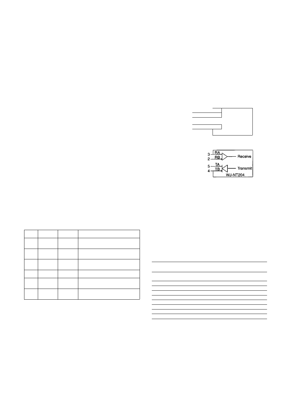
RS-485 Host Port [RS-485 HOST PORT]
Use this when connecting with another WJ-NT204 unit
to operate them from a single controller such as a PC
through the RS-485 daisy chain. Make certain to set the
DIP switch #9 on the front panel to OFF when using this
port. (RJ-11)
RS-485
Host port
RS-485 Data port
m
6 5 4
1 1 1
3 2 1
1 1 1
1 1 1
GNDA B
1 1 1
A BGND
1_1
1_1
TransmitReceive
Straight
For PC
RflJ>
Receive
Transmit
WJ-NT204
®
Setup DIP Switch [SETUP]
A 6-bit DIP switch is provided with the following func
tion. The default position is marked with V See INSTAL
LATIONS on how to set these switches.
Bit#
OFF
ON
Function/Note
#1
Open*
Terminate
Termination on Transparent
Receiving side
#2
Open*
Terminate
Termination on Transparent
Transmission side
#3
Receiver*
(Straight)
Transmitter
(Cross)
RS-485 DATA PORT wiring
exchange
#4
RS-485'
RS-232C DATA PORT selection
#5
Open’
Terminate
Termination on Host Receiving
side
#6
Open*
Terminate
Termination on Host Transmission
side
RS-485 Data Port [RS-485 DATA PORT]
Use this when connecting with other PS*Data
(Panasonic Security) devices such as WJ-MP204 Data
Multiplex Unit, WJ-FS409 Video Multiplexer and so forth
to operate them from a Remote Controller through the
RS-485 chain.
The DIP switch #4 on the rear panel must be set to OFF
when using as an RS-485, or to ON as an RS-232C.
The DIP switch #3 on the rear panel changes terminal
wiring either Straight or Crossover as shown below.
(RJ-11)
This switch is set to OFF for a Receiver, and ON for a
Transmitter when CCTV devices are connected.
Straight
(Receiver)
F=T
Crossover
(Transmitter)
j
:
L-
ATAPDH'
DkTA
HCRT
6 5 4
1 1 1
3 2 1
1 1 1
6 5 4
1 I i
3 2 1
1 1 1
1 1 1
GNDA B
1 1 1
A BGND
1 1 1
GNDA B
1 1 1
A BGND
1_1
1_1
1_1
1_1
TransmitReceive
Receive
Transmit
Crossover (Transmitter)
3
TA
KF
For
^ 2
TB,
— Transmit
Matrix
Switcher
c
RA
A
_ RB,
— Receive
WJ-NT204
Straight (Receiver)
For
_
System Controller
ex.) WV-CU360
RS-232C Data Port [RS-232C DATA PORT]
Use this when communicating with other RS-232
devices through D-Sub 9-pin connector. The pin func
tion is basically the same as the RS-232C HOST port
on the front panel.
RS-232C
DATA PORT
RS-232C Data Port
No.
Signal
name
Function
Direction as seen from
WJ-NT204
1
C D
Receiver carrier
detection
Input
2
R D
Receiving data
Input
3
SD
Sensing data
Output
4
E R
Data connection ready
Output
5
SG
Signal Ground
-
6
D R
Data set ready
Input
7
R S
Request send
Output
8
CS
Send enabled
Input
9
N. C.
(Not used)
(g) Ethernet Port [10BASE-T/100BASE-TX]
Connect the 10/100BASE-T terminal to an Ethernet with
a 10BASE-T or 100BASE-TX cable.
Signal Ground [SIGNAL GND]
AC Inlet [AC IN]
14