Front view, Power switch & power indicator [power, D [link/10base-t] indicator – Panasonic WV-CU20 User Manual
Page 11: 100base-tx] indicator, Rs-232c host port [rs-232c host port, Connect] indicator, D [act] indicator, D ringer volume control [ring. vol, Ringer buzzer, D reset button [reset
Attention! The text in this document has been recognized automatically. To view the original document, you can use the "Original mode".
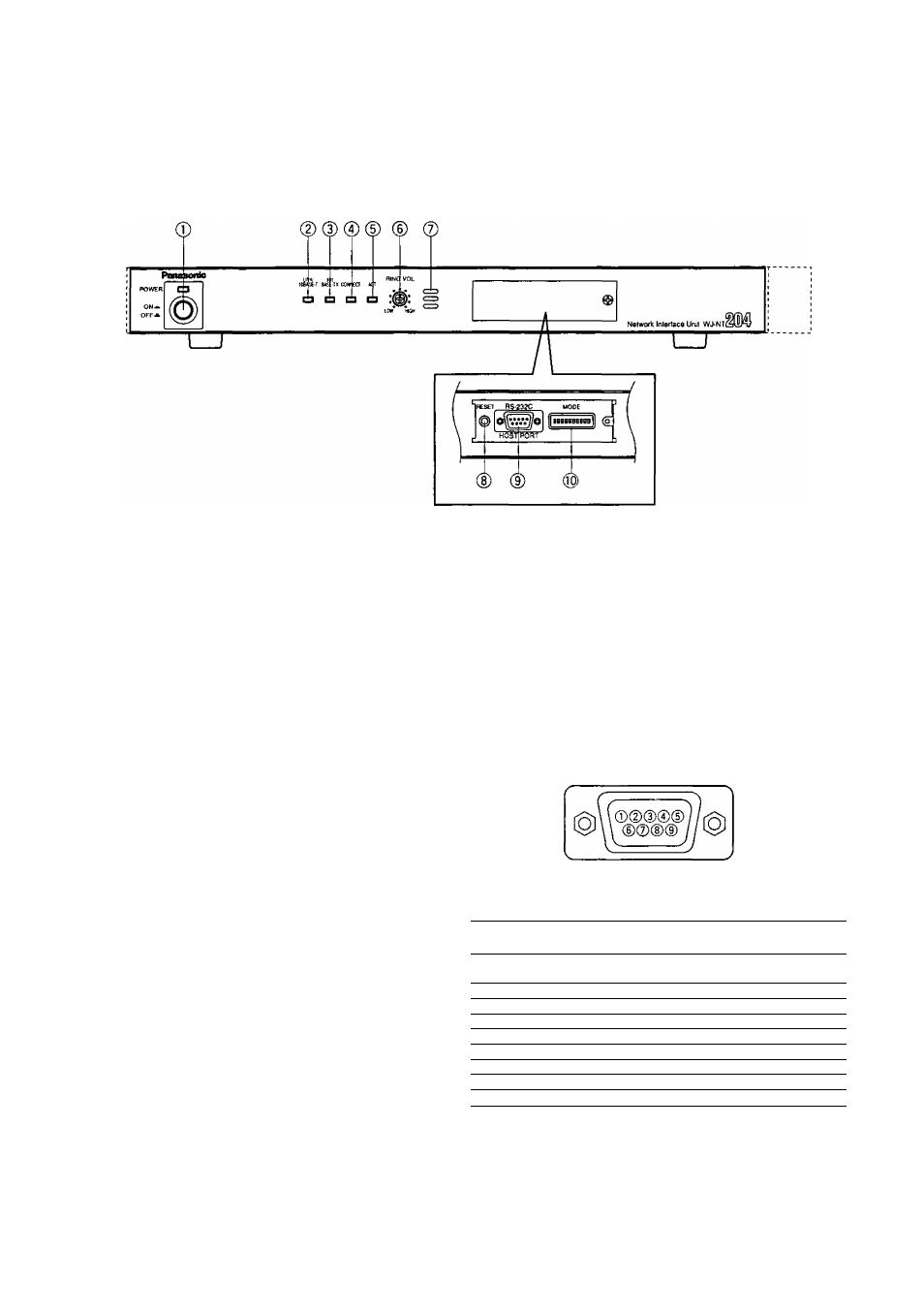
Front View
© Power Switch & Power Indicator [POWER]
Press this switch to turn on or olí the power of the unit.
The indicator lights while the power is turned on.
(D [LINK/10BASE-T] indicator
Lights when communication is established through
lines (LINK) or a 10BASE-T LAN.
@ [100BASE-TX] indicator
Lights when communication is established through a
100BASE-T LAN, along with the LINK/10BASE-T indica
tor.
®
RS-232C Host Port [RS-232C HOST PORT]
The unit communicates with the host computer through
this D-Sub 9-pin connector. Setting the MODE DIP
switch #9 specifies the mode and usable port from
among RS-485 {Rear Panel) and RS-232C (Front
Panel). Available controls are as follows.
• Communication control such as calling and discon
nection
• Up/Download for software
• Download for communication log and alarm log
@ [CONNECT] indicator
Lights when signaling the data only in H.261 mode.
(D
[ACT] indicator
Blinks when receiving and sending IP packets.
(D
Ringer Volume Control [RING. VOL]
Turn this control to adjust the sound level that beeps
when receiving a call.
® Ringer Buzzer
Beeps when receiving a call only in H.261 mode.
(D
Reset Button [RESET]
Pressing this button shuts down the current operation
and restarts the system.
RS-232C
HOST PORT
RS-232C Host Port
No.
Signal
name
Function
Direction as seen from
WJ-NT204
1
CD
Receiver carrier
detection
Input
2
R D
Receiving data
Input
3
SD
Sensing data
Output
4
E R
Data connection ready
Output
5
SG
Signal Ground
-
6
D R
Data set ready
Input
7
RS
Request send
Output
8
CS
Send enabled
Input
9
N. C.
(Not used)
11