On the control site (receiver), Control site connection, 1 v e 0 1 – Panasonic WV-CU20 User Manual
Page 31
Attention! The text in this document has been recognized automatically. To view the original document, you can use the "Original mode".
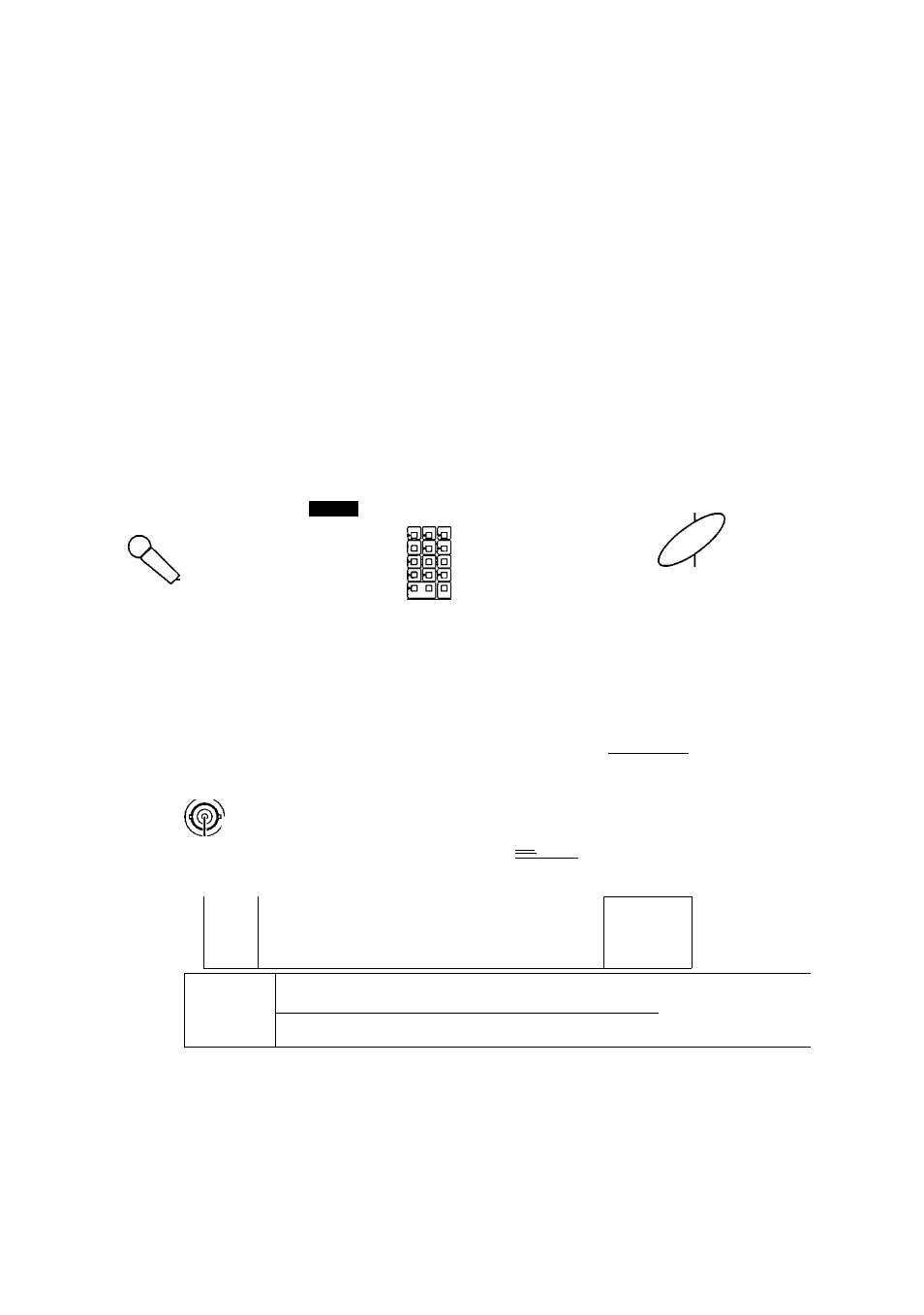
■ On the Control Site (Receiver)
Connections on the Control site is outlined below in the figure.
1. MONITOR Connection
Connect the MON/SPOT terminal to the monitor.
Connect the AUDIO OUT terminal to the monitor.
2. PARALLEL IN-OUT Connections
Connect the PARALLEL OUT terminals with Auxiliary devices (e.g., an electric lamp and a relay). These devices will be
activated when optional switches connected to the PARALLEL IN terminals are closed on the Remote site.
Connect the PARALLEL IN terminals with optional switches to control the Auxiliary devices on the Remote site.
3. Connect the REMOTE terminal to the WV-CU20 Remote Controller with the supplied cable {6-conductor, straight wiring,
included in the WV-CU20).
4. Connect the RS-485 DATA PORT to a WV-CU360 System Controller with RS-485 cable. The WV-CU360 will control
PS*Data equipment on the Remote site through the network, and will also control the Control site equipment.
5. Connect the 10/100BASE-T terminal to an Ethernet with a 10BASE-T or 100BASE-TX cable.
Remote Controller
WV-CU20
System Controller
ex.) WV-CU360
i f -
Amplifier
Microphone
>1
□ □CD
□ □□
QQO
0DS
□ □ □□□
Network
Interface Unit
(Receiver)
ID O [3
a aiD
a a a
gog
§ cm
a
To Network
I N
-AUX
MON/
ytxrrS
ÍPOT AU
OUT
)IO
uB
10/100BASE-T Cable
SENSOR IN/TRIGGER OUT
I
oooooooooooo
ooooooo
ÜÜ
REMOTE HOST PORT
nS-486-
PARALLEL PORT
oooooooooooo
O O O O O O O O O O O O i
Q
RS-232C
ooooo
oooo
SETUP DATA PORT
n n
p—'
1
DATA PORT
□
10BASE-T/100BASETX
f Receiver does not use.
Auxiliary Devices
1 V E 0 1
1 1 2 3 4 5 6 7 8
1 o*OíOíO-OiO-íS#íSí
J
1 1 1
Lamp Buzzer Relay !
Auxiliary Control Switc
Monitor
Control Site Connection
31