Dyno electronics symbols, Dyno electronics symbols -5 – Dynojet WinPEP 7 User Manual
Page 21
D Y N O A N D W I N P E P B A S I C S
Dyno Electronics
Version 2
WinPEP 7 User Guide
2-5
D
YNO
E
LECTRONICS
S
YMBOLS
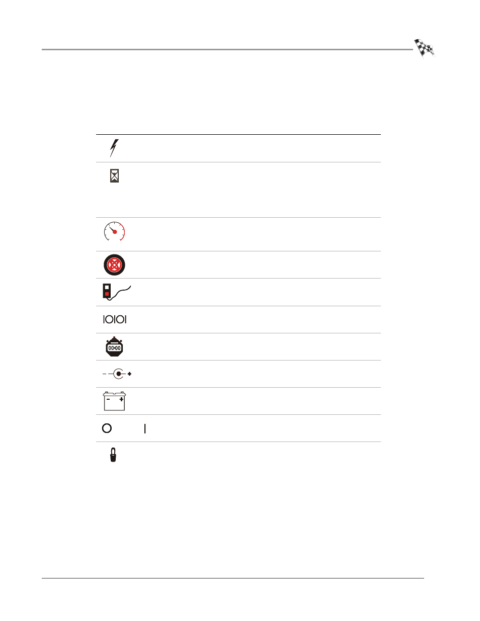
Symbols on the dyno electronics modules help you understand their function.
A description of the module symbols and functions follows.
For more information on connecting your dyno electronics, see “Connecting the
Dyno Electronics” on page 3-11.
symbol
description
Shows when the module is receiving power.
CPU module: the blue LED is lighted when data from
the modules is being acquired and saved.
Input/Output module: the amber LED flashes
proportionally to the dyno drum rpm.
Atmospheric Sensing module: the flashing amber LED
indicates the module processor is operating properly.
Inputs for both primary and secondary inductive
pickup clips. Either input may be used with a primary
or secondary inductive pickup on a single ended coil.
Both inputs can be used for a wasted spark ignition.
Connects to the 25-pin shielded cable from the
dynamometer.
Connects to the 9-pin pendant cable.
Connects to the 9-pin RS-232 PC serial
communications port.
Connects a synchronization signal to a third party data
acquisition system.
Connects a 12 volt DC power to a third party data
acquisition system.
Connects to a 12 volt DC power supply or battery.
The adjacent LED glows bright green when power is
properly connected.
When this switch is on, power is supplied to all
connected modules.
Amber LED flashes at a steady rate when the power is
on; flashes proportionally to the rpm when an rpm
signal is detected, faster rpm equals faster blinking
rate.