Dyno electronics – Dynojet WinPEP 7 User Manual
Page 20
WinPEP 7 User Guide
C H A P T E R 2
Dyno Electronics
2-4
. . . . . . . . . . . . . . . . . . . . . . . . . . . . . . . . . . .
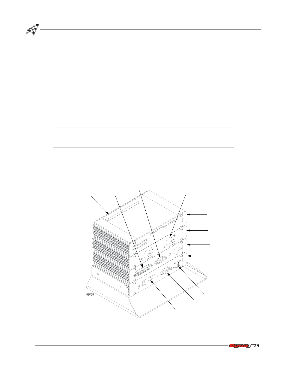
DYNO ELECTRONICS
The standard dyno electronics package is comprised of four interconnected modules:
Figure 2-1: Dyno Electronics
module
description
CPU Module
Contains a 32-bit processor which acquires data from the
expansion modules and communicates to the main
computer running the WinPEP software. The processor
queries the expansion modules to determine their identity
and capabilities.
Input/Output Module
Sends and receives data from the dyno and the pendant.
This module also contains a buzzer and a light which are
activated when either the vehicle or the dyno speed limit
is approached.
RPM Module
Receives and processes signals from up to two inductive
pickups for measurement of engine RPM. Each input has
an automatic gain circuit to compensate for a wide
variance of ignition systems.
Atmospheric Sensing Module
Measures absolute pressure, air temperature, and relative
humidity. The measurements are used by WinPEP to
correct power and torque measurements to standard
atmospheric conditions according to a DIN, SAE, or other
formula.
9-pin RS-232 socket
CPU module
atmospheric
sensing module
RPM module
input/output module
9-pin hand
held pendant
3-pin power
plug
system expansion
connector
inductive pickup
socket
25-pin socket
power