Basic pll configuration editor, Basic pll ip configuration editor, Basic pll configuration – Achronix ACE Version 5.0 User Manual
Page 32: Editor
Editors
Chapter 3. Concepts
Basic PLL Configuration Editor
The Basic PLL Configuration Editor provides a simplified graphical wizard for creating a PLL configuration
file (.acxip). This editor allows the user to generate the required configuration files for design with the
embedded PLLs. See
. Unlike the much more complicated
, the Basic PLL Configuration Editor allows the user to access only the most-often used
functionality of the PLL.
By default, the Basic PLL Configuration Editor is included in the IP Configuration perspective
(Window→Open Perspective→IP Configuration) (
). The Basic PLL configuration information fits into a
single page.
Once the user has configured the PLL to meet their requirements, and the Basic PLL Configuration Editor
has determined that there are no errors in the configuration, the user may choose to generate their IP design
files (see
Generating the IP Design Files
NOTE:
The Basic PLL only supports Pure Internal Feedback Mode, and thus hides feedback path
modes from the user. This allows fractional feedback dividers (so any desired clkout0
output frequency is achievable), but prohibits deskew functionality. For simplification,
output phase adjustment is also disabled. If deskew or phase adjustment functionality are
required, the Advanced PLL must be used instead of the Basic PLL.
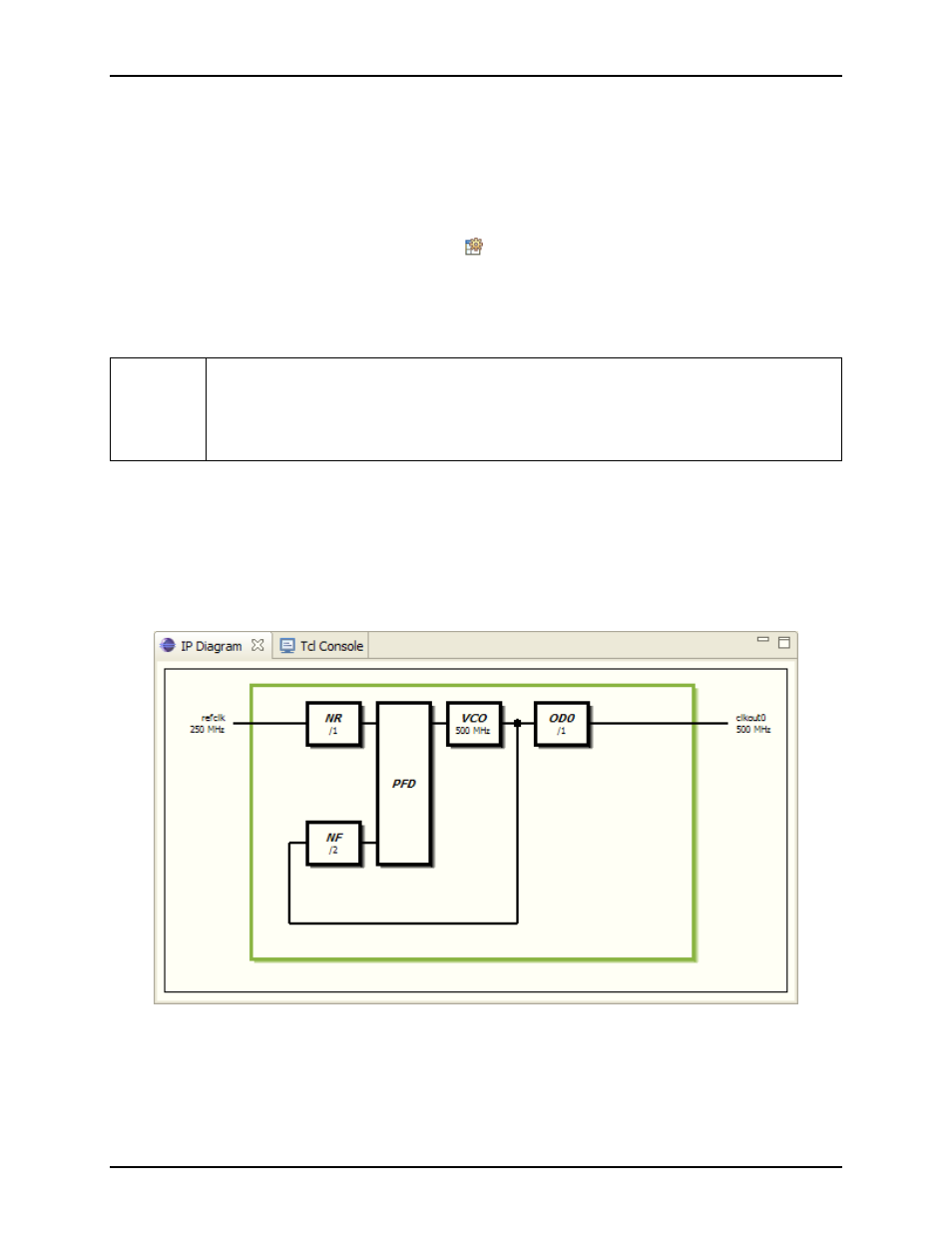
IP Diagram
The
for the Basic PLL shows live information about the current configuration in the Editor,
including which logic blocks are currently active, which inputs and outputs are currently active, and what
the various frequencies are within the PLL. Additionally, configuration errors will be shown with a red
background, and configuration warnings will be shown with a yellow background (these are the default IP
Diagram colors, and may be modified in the Preferences).
Figure 3.10: Example IP Diagram for PLL
UG001 Rev. 5.0 - 5th December 2012
20