Achronix ACE Version 5.0 User Manual
Page 161
Views
Chapter 3. Concepts
Critical Path Diagram View Toolbar Buttons
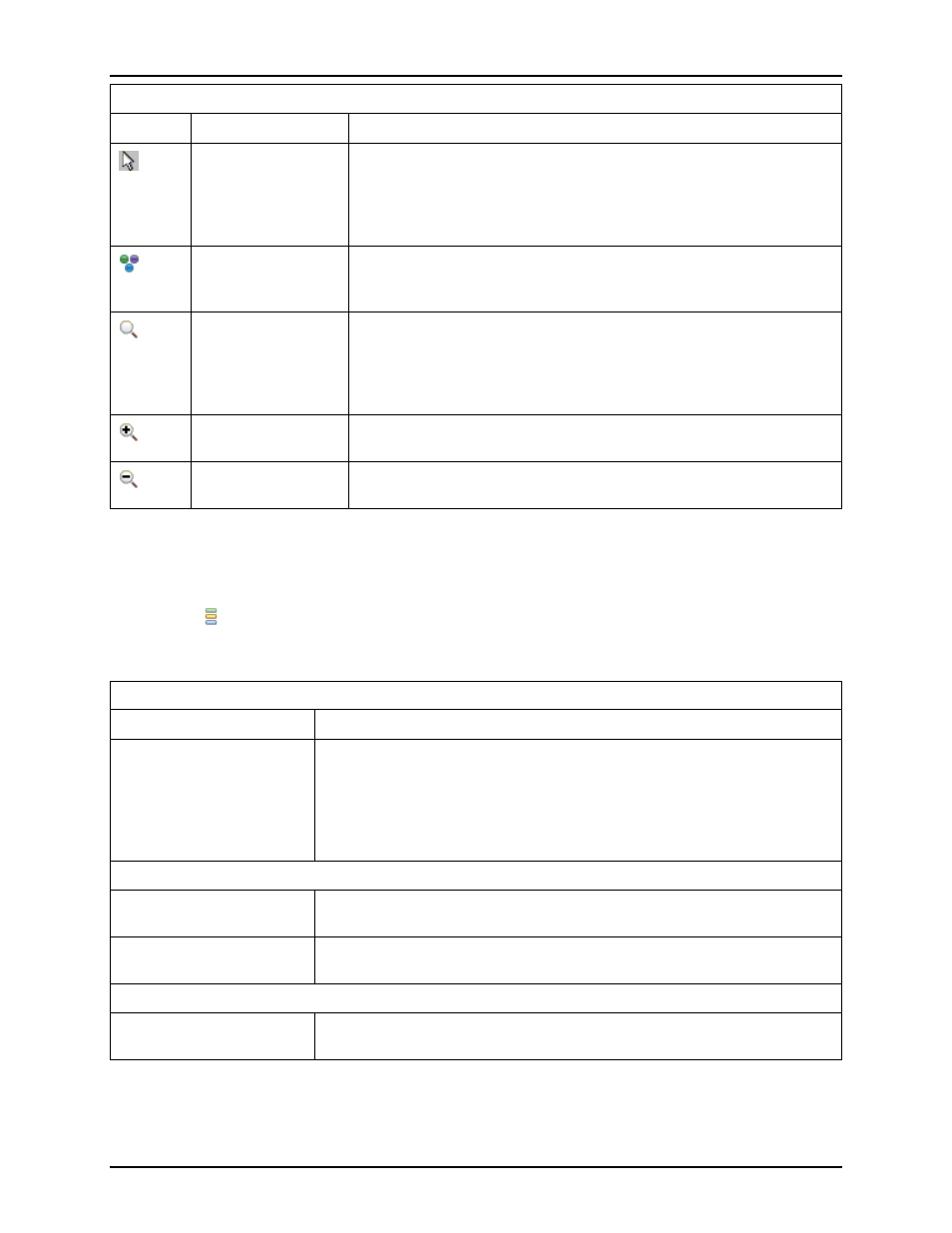
Icon
Action
Description
Selection tool
Controls the behavior of the mouse while in the Critical Path
Diagram view. The selection tool creates a selection rectangle when
the left mouse button is pressed and held. Any objects in the
selection rectangle are applied with the current selection action, as
configured in the
Movement tool
Controls the behavior of the mouse while in the Critical Path
Diagram view. The movement tool pans the view when the left
mouse button is pressed and held.
Zoom tool
Controls the behavior of the mouse while in the Critical Path
Diagram view. The zoom tool creates a zoom-in rectangle when the
left mouse button is pressed and held, then dragged to the
lower-right. The zoom tool creates a zoom-out line when the left
mouse button is pressed and held, then dragged to the upper-left.
Zoom in
Increases the current zoom level in the Critical Path Diagram view by
200%.
Zoom out
Decreases the current zoom level in the Critical Path Diagram view
by 200%.
Fly-Out Palette
The following options are available in the fly-out palette in the Critical Path Diagram view:
Layers
The
Layer Options control the layers of visible data in the Critical Path Diagram view, allowing a
user to control the amount of visible data, and for reconvergent paths (RC Paths), control how the displayed
data is presented.
Layer Options
Option
Description
Intermediate Nodes
When selected, this adds additional smaller Intermediate Nodes to the
diagram’s graph. The intermediate nodes are any instances which are not
Turn Points, but are still part of the data flow between Turn Points.
Enabling this will also cause the arrows connecting the nodes to represent
individual nets instead of abstractions representing one-or-more nets and
the intervening instances.
RC Path Topology
Driver→Sink
Graph topology for reconvergent paths is arranged so that user logic
Drivers are on the left, and user logic Sinks are on the right.
Polygon
Graph topology for reconvergent paths is arranged so that the nodes are
in a balanced polygon, like a square, pentagon, hexagon, octagon, etc.
RC Path Arrows
User Logic
Arrows connecting nodes for a reconvergent path diagram will point in
the direction the data flows through the user’s logic.
149
UG001 Rev. 5.0 - 5th December 2012