Achronix ACE Version 5.0 User Manual
Page 287
Analyzing Critical Paths
Chapter 4. Tasks
hidden due to insufficient drawing area.
Arrows
The arrows connecting the graph nodes in the diagram represent the nets connecting the object
instances. They too can display various pieces of information that may be enabled and disabled via the
. In addition to the arrow’s direction, the line types making up the arrow also represent important
information.
Bold arrows, visible when the Intermediate Nodes
setting is disabled, represent one or
more nets and any hidden intermediate nodes, lumped into a single abstraction. Bold arrows, since they
potentially represent multiple nets and hidden intermediate instances, may only display text for their
cumulative ps of Delays and (for asynchronous designs) their cumulative count of Pipeline Stages. Net
Names
and Fanouts are never displayed for bold arrows, since they make no sense in this context.
Skinnier arrows will be shown when the Intermediate Nodes
setting is enabled - these will
each represent an individual net. Because these skinnier arrow each represent individual nets connecting
the instances, the individual nets’ Fanouts and Net Names may also be displayed for each arrow, in addition
to the Delays and (for asynchronous designs) Pipeline Stages.
Arrows made with dotted lines, used only for reconvergent path type diagrams in asynchronous designs,
will indicate signals flowing in the direction opposite to the User Logic. These are for the underlying async
’acks’ (backward tokens) backward-propagating along the net, necessary for all async communication.
These backward-propagation signals are normally hidden/abstracted away so the user doesn’t need to
think about them, but they are made visible out of necessity during reconvergent path critical path timing
analysis.
Critical Path Diagram Types
Different types of critical paths have different visual representations. (The Type column in the
’s table provides the critical path type of each row.)
All path types in synchronous designs (and several types in asynchronous designs) are displayed as a
straight line of objects connected by arrows.
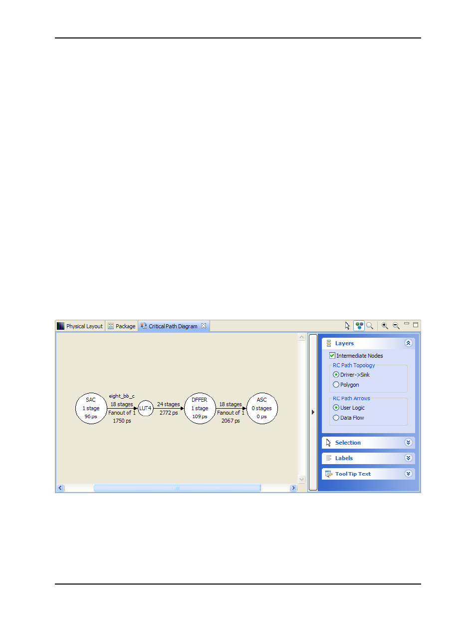
Figure 4.8: Critical Path Diagram View for Underfilled Pipeline
Other asynchronous-specific critical path types, like Loops, will be shown as circles of nodes connected by
arrows.
275
UG001 Rev. 5.0 - 5th December 2012