Type m-flat connectors, Female connectors – Northern Connectors Harting DIN 41 612 Connectors User Manual
Page 69
01
.
43
78 + 2
b)
60 + 4
42 + 6
24 + 8
f)
78 + 2
60 + 4
42 + 6
24 + 8
78 + 2
60 + 4
42 + 6
24 + 8
Y
DIN
S
ig
na
l
up t
o 2 A
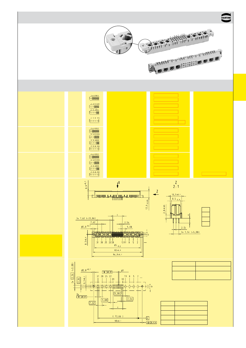
DIN 41 612 · complementary type M-flat
Female connectors
Number of contacts
78+2, 60+4,
42+6, 24+8
Female connector
with solder pins
2.9 mm
(without special contacts)*
Performance level 3
on request
Number Contact
Identification
of contacts arrangement
Part No. Performance levels according to IEC 60 603-2. Explanation chapter 00
3 2 1
Board drillings
Mounting side
Dimensions
in mm
Type
row
position
all holes
* Pre-loaded with special contacts on request
b)
Connectors with snap-in clips see chapter 00
f)
Railway classification NFF 16-101, Smoke index: F1, Flammability class: I2
c
78 + 2 25 x 2.54 = 63.5
0
60 + 4 19 x 2.54 = 48.26
42 + 6 13 x 2.54 = 33.02
24 + 8 7 x 2.54 = 17.78
Female connector
with solder pins
4.5 mm
(without special contacts)*
Female connector
with press-in pins
4.5 mm
(without special contacts)*
Dimensions
Solder pins
Press-in pins
row
position
a
2.9
4.5
4.5
Board drillings depend on
type and special contact
loading
Y
Solder
1 ± 0.1
Press-in
see recommendation
page 00.25
Order high current,
high voltage, coaxial
and fibre optic contacts
separately, see pages
01.38 ff