Technical characteristics type h – Northern Connectors Harting DIN 41 612 Connectors User Manual
Page 148
04
.
10
5 V
5 mA
DIN
P
ow
er
up t
o 1
5 A
Technical characteristics
Type H
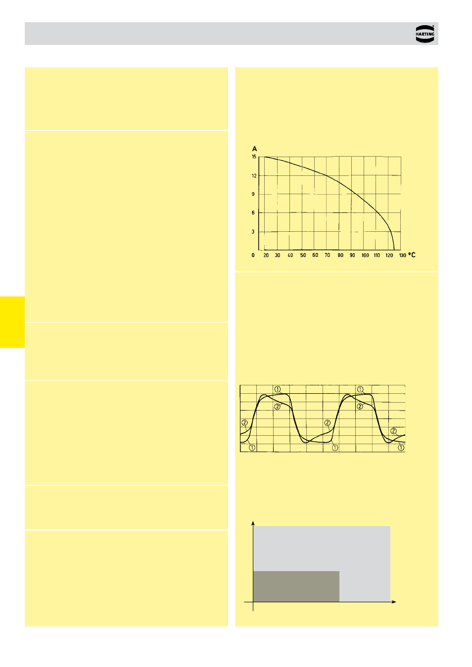
Current carrying capacity
The current carrying capacity is limited by maximum temperature of
materials for inserts and contacts including terminals. The current
capacity curve is valid for continuous, non interrupted current loaded
contacts of connectors when simultaneous power on all contacts is
given, without exceeding the maximum temperature.
Control and test procedures according to DIN IEC 60 512
W
or
king current
Ambient temperature
Recommendation
Gold
Silver
Low currents and voltages
Type H standard contacts have a silver plated surface. This pre-
cious metal has excellent conductive properties. In the course of a
contact’s lifetime, the silver surface generates a black oxide layer
due to its affinity to sulphur. This layer is smooth and very thin and
is partly interrupted when the contacts are mated and unmated,
thus guaranteeing very low contact resistances. In the case of very
low currents or voltages small changes to the transmitted signal
may be encountered. This is illustrated below where an artifically
aged contact representing a twenty year life is compared with a
new contact.
In systems where such a change to the transmitted signal could
lead to faulty functions and also in extremely aggressive environ-
ments, HARTING recommend the use of gold plated contacts.
Below is a table derived from actual experiences.
Changes to the transmitted signal after artifical ageing
➀
new contact
➁
after ageing
Number of contacts
15, 16
14 + 1 leading contact
(position z 32)
13 + 2 leading contacts
(position z 4 und z 32)
3
Working current
15 A max.
see current carrying capacity chart
Clearance
Type H15:
≥ 4.5 mm
Type H3:
≥ 4.0 mm
Creepage
Type H15:
≥ 8.0 mm
Type H3:
≥ 3.7 mm
Working voltage
The working voltage also depends according to the safety
on the clearance and creepage
regulations of the equipment
dimensions of the pcb itself and
Explanations see chapter 00
the associated wiring
Connectors should not be
mated under voltage
Test voltage U
r.m.s.
Type H15:
≥ 3.1 kV
Type H3:
≥ 2.5 kV
Contact resistance
≤ 8 mΩ
Insulation resistance
≥ 10
12
Ω for standard articles
≥ 10
11
Ω for special NFF articles
(with part-no. ending 222)
Temperature range
– 55 °C … + 125 °C
The higher temperature limit
includes the local ambient and
heating effects of the contacts
under load
Electrical termination
Connector with faston
6.3 x 2.5 (faston blade
width x wire gauge)
according to DIN 46 245
and DIN 46 247
Solder pins for pcb
connections Ø 1.6 ± 0.1 mm
DIN EN 60 097
Cage clamp terminal
0.14-1.5 mm²
Insertion and withdrawal force
Type H15:
≤ 90 N
Type H3: ≤ 20 N
Materials
Mouldings
Thermoplastic resin,
glass-fibre filled, UL 94-V0
Contacts
Copper alloy
Contact surface
Contact zone
Hard silver plated or
gold plated
Mating conditions
see chapter 00
Coding systems
see chapter 00