Creepage and clearance distances, cti, How to identify the maximum voltage – Northern Connectors Harting DIN 41 612 Connectors User Manual
Page 11
00
.
05
60
63
32
63
110
120
125
80
125
127
150
2)
160 – 160
208
200 125 200
220
230
250 160 250
240
300
2)
320 – 320
380
400
400 250 400
415
440
500 250 500
480
500 320 500
500
575
630 400 630
600
2)
630 – 630
660
630 400 630
690
720
800 500 800
830
960
1000 630 1000
1000
2)
1000 –
1000
Gen
er
al
in
fo
rma
tio
n
Creepage and clearance distances, CTI
50
0.33
0.50
0.80
1.5
100
0.50 0.80 1.5 2.5
150
0.80
1.5 2.5 4.0
300
1.5 2.5 4.0 6.0
600
2.5 4.0 6.0 8.0
1000 4.0 6.0 8.0 12.0
Table 00.01
Voltages phase-to-earth
derived from rated system voltages
up to U
r.m.s.
and U
–
I
II
III
IV
Rated impulse withstand voltages in kV for installation category
(Voltage form: 1.2/50 µs according to DIN IEC 60060-1)
Table 00.02
Minimum clearances in mm up to 2000 m above sea level
1)
Pollution degree
Pollution degree
Case A
Case B
(Inhomogeneous field
3)
)
(Homogeneous field
2)
)
1 2 1 2
Rated impulse
withstand
voltage in kV
0.33
0.01 0.01
0.50
0.04 0.2 0.04 0.2
0.80
0.1 0.1
1.5 0.5 0.5 0.3 0.3
2.5 1.5 1.5 0.6 0.6
4.0 3
3 1.2 1.2
6.0 5.5 5.5 2
2
8.0 8
8 3
3
1)
For higher altitudes see table 2b from DIN VDE 0110 for multiplying factors.
2)
Verification by an impulse voltage test is required if the clearance is less than the value specified for case A.
3)
Point to plane.
Table 00.03 a.
Single phase, three or two wire AC
or DC systems
Table 00.03 b.
Three phase, four or three wire
AC systems
Rated voltage in V
Nominal
voltage
of supply
system
1)
U
r.m.s.
or U
–
in V
Phase-to-
phase
All systems
(between
conduc tors of
different polarity
for U
–
)
U
r.m.s.
or U
–
Rated voltage in V
Nominal
voltage
of supply
system
1)
U
r.m.s.
in V
Phase-
to-
phase
All
systems
U
r.m.s.
Phase-to-earth
Phase-to-
earth
U
r.m.s.
or U
–
U
r.m.s.
U
r.m.s.
12.5
12.5
–
24
25 –
25
30
32 –
42
48
50 –
50
2)
60
63 –
60/30
63
32
100
2)
100 –
110 125 –
120
150
2)
160 –
220 250 –
220/110 250 125
240/120
300
2)
320 –
440/220 500 250
600
2)
630 –
480/960 1000 500
1000
2)
1000 –
1)
This voltage can be the same as the rated voltage of the equipment.
2)
These values correspond to the values of table 00.01.
In countries where both star and delta, earthed and unearthed supply systems are used the values for delta
systems only should by used. Systems earthed across impedances are treated as unearthed systems.
Table 00.04
Rated voltage (V)
U~
r.m.s.
or U_
12.5
25
32
50
63
80
100
125
160
200
250
320
400
500
630
800
1000
Minimum creepage distance (mm)
Degree of pollution 1:
CTI group II + III a/b
0.09 0.125 0.14
0.18
0.2
0.22
0.25
0.28
0.32
0.42
0.56
0.75
1
1.3
1.8
2.4
3.2
Degree of pollution 2:
CTI group III a/b
0.42 0.5
0.53
1.2
1.25
1.3
1.4
1.5
1.6
2
2.5
3.2
4
5
6.3
8
10
CTI group II
0.42 0.5
0.53
0.85
0.9
0.95
1
1.05
1.1
1.4
1.8
2.2
2.8
3.5
4.5
5.6
7.1
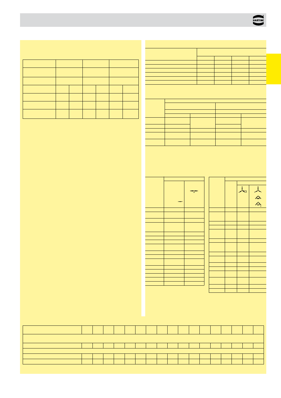
Exemplary calculation
What voltage can be used, if the creepage, the installation category
and the degree of pollution are known:
Creepage
1.2 mm
3.0 mm
8.0 mm
Installation
category
II
II
II
Degree of polution
2
2
2
CTI-Value
< 400 > 400 < 400 > 400 < 400
> 400
Isolation group
III a/b
II
III a/b
II
III a/b
II
Rated voltage
50 V
160 V 250V 400 V 800 V 1,000 V
Nominal voltage
of supply system
50 V
150 V 220 V 380 V 720 V 1,000 V
How to identify the maximum voltage
1. Define the installation category
2. Define the degree of pollution expected
3. Select the rated impulse withstand voltage in kV from table 00.02
4. Select the voltage phase to earth derived from rated system voltages
from table 00.01
5. Select the rated voltage from table 00.04
6. Define the number of phases and whether table 00.03 a
or table 00.03 b is relevant for the application
7. Select the nominal voltage of supply system from table 00.03 a
or 00.03 b
8. Select the lower voltage from point 4 and 7