Specifications, assembly instructions, Design of connectors, Building up card frame systems – Northern Connectors Harting DIN 41 612 Connectors User Manual
Page 13: Complementary components
00
.
07
Gen
er
al
in
fo
rma
tio
n
Specifications, assembly instructions
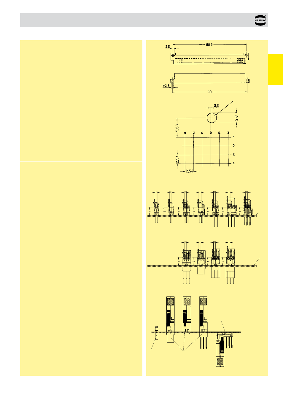
Mounting hole
Type F
Interface connector U
Type F
Distributor
Type F
Interface connector I
Contact spacing
g = 12.4 -14.2
f = 3.55
g = 12.4 -14.2
f = 3.55
Design of connectors
●
Standard fixing arrangement
●
Standard positions for pcb´s and connectors provide a modular
system in the card frame and a standard front panel system.
●
Standard wiring matrix on the connection side for female connectors
built up on a 2.54 mm (0.1" centres) grid. (This facilitates automatic
wiring).
●
Printed circuit boards with standard dimensions 100 x 160
resp. 233.4 x 160 mm as set out in DIN EN 60 297-3 standard sizes
3 U and 6 U.
Building up card frame systems
In the basic frame unit according to DIN EN 60 297-3 pcb’s are
insert ed from the front and make contact with the connectors fitted
to the back. This basic arrangement gives the following advantages:
●
When using conventional connectors on the back of the card frames,
space is left above, below and in the middle along the hor izontal
line of the frame which can be used to fit extra connectors for cross
connection or making plug connections by means of flying lead
connectors.
●
Using the HARTING system one can also connect flying lead
connectors onto the front of the frame or even onto the inside of the
back of the frame. This means that external equipment can easily
be monitored, controlled or tested from the card frame itself.
Complementary components
All connectors can be supplied with a complete range of accessories.
These can be fitted above or below the wiring plane on the back of
the card frame or on the front of the card frame. These connectors
and accessories provide a complete connector system suitable for
commonly used wiring techniques.
●
The flying lead connector consists of a connector with crimp or
solder contacts and a shell housing. The flying lead connector is
latch ed or retained in position using screw fixings and is compatible
with a corresponding male connector and interface connectors I
and U.
●
Fixing brackets prohibit the withdrawal of the pcb when a flying lead
connector is used on the front side of the card frame.
●
The interface connector I has blade contacts on the plug side and
solder pins, wrap posts or crimp terminals on the termination side.
It replaces the female connector type F fitted into the frame and
allows interfacing to the internal wiring with the help of the flying
lead connector on the back of the card frame unit.
●
On the one plane the interface connector U has male contacts that
are compatible with the flying lead connector. On the other plane
it has wrap posts for interfacing to the internal wiring of the card
frame. It can be mounted on the back of the card frame above
or below other connectors arranged upright. Its wrap posts follow
the same pitch as other connectors therefore allowing automated
wiring. By using the U connector with the flying lead connector
plug-in connections between the card frame and the peripheral
equipment/ out lying stations are made easy.
Type
B Q C R D E har-bus 64
Type
F H MH
Mounting
level
Mounting
level