Max . 32, Female connectors – Northern Connectors Harting DIN 41 612 Connectors User Manual
Page 114
03
.
14
32
f)
32
c)f)
1
2
3
1
2
3
1
2
3
FC 1
FC 2
FC 3
DIN
P
ow
er
up t
o 6 A
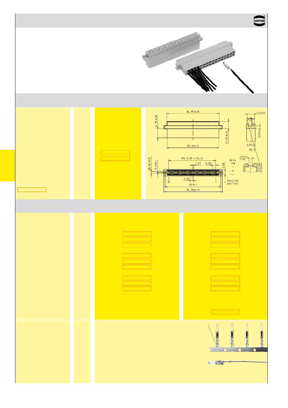
DIN 41 612 · Type D
Female connectors
Number of contacts
max . 32
Number
Identification
of contacts
Part No .
Drawing
Dimensions in mm
Female connector
for crimp contacts
Order contacts separately
Female crimp FC
contacts
Bandoliered contacts
(approx . 2,500 pieces)
Bandoliered contacts
(approx . 250 pieces)
Individual contacts
1)
Wire gauge
Insulation ø
mm²
AWG mm
3 .5 + 0 .5 mm of insulation is stripped from the wires
to be crimped
For the fabrication in line with the specification please
use exclusively crimp tools approved by HARTING
(see DIN EN 60 352-2)
Insertion, removal and crimping tools see chapter 30
Identification
Identification
Wire gauge
Part No . Performance levels according to IEC 60603-2 . Explanation chapter 00
2
1
Identification
Bandoliered
contacts
Individual contacts
Shell housing
see chapter 20
1)
Packaging unit 1,000 pieces
2)
Solder contacts must not be used together with shell housing A . Special contact surface: 2 µm gold .
c)
Connectors with coding see chapter 00
f)
Railway classification NFF 16-101, Smoke index: F1, Flammability class: I2
Female contacts with
solder lugs
2)
(lockable)
1
0 .09 - 0 .25
28 - 24
0 .7 - 1 .5
2
0 .14 - 0 .56
26 - 20
0 .8 - 2 .0
3
0 .5 - 1 .5
20 - 16
1 .6 - 2 .8