Iii i ii, High voltage contacts – Northern Connectors Harting DIN 41 612 Connectors User Manual
Page 65
01
.
39
IV
III
III
I
II
I
II
IV
DIN
S
ig
na
l
up t
o 2 A
DIN 41 612 · Special contacts type M
Part No.
Identification
Performance level 1
Drawing
Dimensions in mm
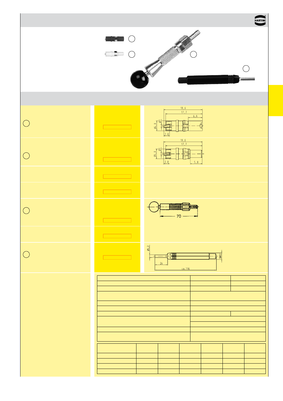
High voltage contacts
High voltage male contact
for male connectors
2)
for straight solder
termination
2.8 kV
Impedance
50 Ω
75 Ω
Max. working frequency
0 up to 10 GHz
0 up to 1.5 GHz
Return loss
≥ 20 dB up to 6 GHz
≥ 20 dB
RF-leakage
≥ 80 dB up to 0.5 GHz
≥ 68 dB up to 1.5 GHz
Test voltage
750 V
rms
Working voltage
250 V
max.
Insulation resistance
≥ 1 GΩ
≥ 200 MΩ
Contacts resistance – Center contact
– Outer contact
≤ 10 mΩ
≤ 3 mΩ
Contact current max.
1.5 A
Admissible power (depends on: frequency, applica-
tion, return loss, environmental characteristics)
Data on request
acc. to DIN 41 626
Crimping tool
for coaxial contacts
Removal tool
incl. removal jacket
for contact replacement
in male and female connectors
Removal tool
for contact replacement
in male connectors
Replacement removal jacket
Electrical characteristics
of coaxial contacts
and wires
Crimping tool
for high current contacts
1)
Contact resistance max. 1.5 mΩ
2)
Contact resistance internal wire max. 3 mΩ
2.8 kV
High voltage female contact
for female connectors
2)
for straight solder
termination
Cable group 2
flexible wires
Impedance
Shell
ø
Screening
ø
Dielectric
ø
Internal wire
ø
Hexagonal crimp
Spanner width
RG 174 A/U
50 Ω
2.5
2.0
1.5
0.48
3.25
RG 188 A/U
50 Ω
2.6
2.0
1.5
0.54
3.25
RG 316 U
50 Ω
2.5
2.0
1.5
0.54
3.25
RG 179 B/U
75 Ω
2.54
2.0
1.6
0.3
3.25