Type f connectors, Male connectors – Northern Connectors Harting DIN 41 612 Connectors User Manual
Page 127
03
.
27
48
f)
b)
b)f)
48
d)
b)d)
b)d)
32
b)
f)
32
f)
b)
b)
47 + 1
b)
31 + 1
46 + 2
222
f)
SMC
DIN
P
ow
er
up t
o 6 A
Part No . Performance levels according to IEC 60603-2 . Explanation chapter 00
3 2 1
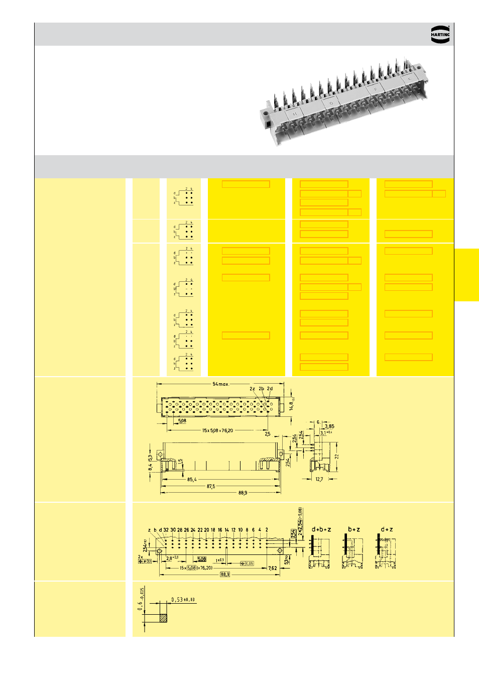
DIN 41 612 · Type F
Male connectors
Number of contacts
48, 32
Number
Contact
Identification
of contacts arrangement
Male connector
with angled
solder pins
1)
1 leading contact
(position z 32)
2 leading contacts
(positions b 2 + b 32)
Dimensions
Board drillings
Mounting side
Dimensions in mm
all holes
Angled
solder pins
1)
With shroud coding, see also chapter 00
b)
Connectors with snap-in clips see chapter 00
d)
CTI > 400
f)
Railway classification NFF 16-101, Smoke index: F1, Flammability class: I2
Cross section of
solder terminations
Cross area (A) of contacts row z, b, d: A = 0 .29 - 0 .34 mm²
- Hummel M40 Circular Power Connectors (20 pages)
- Hummel M27 Circular Connectors (10 pages)
- Hummel M23-Signal - Circular Connectors (32 pages)
- Hummel M23-Power - Circular Connectors (24 pages)
- Hummel M23 RJ45 Circular Connectors (10 pages)
- Hummel M23 Fast Ethernet PoE Circular Connectors (12 pages)
- Hummel M16 Circular Connectors (26 pages)
- Hummel M16 Stainless Steel Connector Housings (10 pages)
- Hirschmann NR-Series Circular Connectors (23 pages)
- Hirschmann CM-Series Plastic Screw Locking Connectors (MIL-C-5015) (11 pages)
- Hirschmann CA-Series Plastic Screw Locking Circular Connectors (2 pages)
- Normek PCB Connectors (2 pages)
- Harting Har-flexicon Connectors (34 pages)
- Harting Har-flex PCB Connectors (17 pages)
- Harting D-sub Connectors, Housings & Accessories (203 pages)
- D-Sub Plastic Hoods (10 pages)
- D-Sub Metalized Plastic Hoods (8 pages)
- D-Sub Full Metal Hoods (22 pages)
- Conec D-Sub Hoods & Accessories (54 pages)
- Lumberg Automation M12 Single-Ended Cordsets (2 pages)
- Lumberg Automation M12 Field-Attachable Cable Connectors (2 pages)
- Mennekes Plugs - IP67 (1 page)
- Mennekes Wall Mounted Inlet (1 page)
- Souriau UT0 Metal Circular Connectors (12 pages)
- Souriau UT0W Metal High Density Circular Connectors (12 pages)
- Souriau UTG Plastic Circular Connectors with Metal Coupling (32 pages)
- Souriau UTL Series Push-Pull Connectors (60 pages)
- Souriau UTP Plastic Circular Connectors (24 pages)
- Souriau UTS Hi Seal Plastic Circular Waterproof Connectors (8 pages)
- Souriau UTS Screw Termination' Plastic Circular Waterproof Connectors (4 pages)
- Souriau UTS Plastic Circular Waterproof Connectors (5 pages)
- Souriau 840 Series Metal Circular Connectors (10 pages)
- Souriau MBG Plastic Circular Connectors (24 pages)
- Souriau Mixed Power / Signal Circular Connectors (5 pages)
- Souriau Overmoulded Cable Assemblies (8 pages)
- Souriau VGE1 / FER1 Ruggedized Metal MIL-DTL-5015 & VG 95234 Connectors (1 page)
- Souriau VGE1 / FER1 Ruggedized Metal MIL-DTL-5015 & VG 95234 Connectors (31 pages)
- Mennekes Panel Mounted Sockets (5 pages)
- Mennekes Panel Mounted Inlet (1 page)
- Mennekes Connectors - IP67 (1 page)
- Mennekes Connectors - IP44 (1 page)
- Lumberg Automation M8 Single-Ended Cordsets (2 pages)
- Alpha Wire XTRA-GUARD Performance Cable (94 pages)
- Alpha Wire Hook-Up Wire (48 pages)
- Alpha Wire FIT Heat-Shrink Tubing (34 pages)