Technical characteristics – Northern Connectors Harting DIN 41 612 Connectors User Manual
Page 100
02
.
10
ha
r-
bu
s 6
4
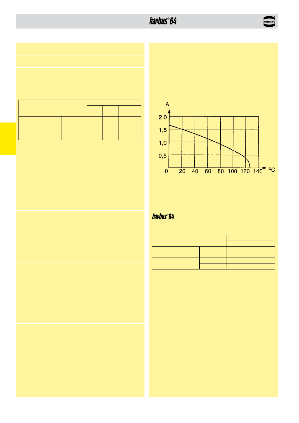
Technical characteristics
according to IEC 61076-4-113
Current carrying capacity chart
The current carrying capacity is limited by maximum temperature of
materials for inserts and contacts including terminals. The current
capacity curve is valid for continuous, non interrupted current loaded
contacts of connectors when simultaneous power on all contacts is
given, without exceeding the maximum temperature.
Control and test procedures according to DIN IEC 60 512
W
or
king current
Ambient temperature
with switches
Deviating technical characteristics for the switching elements.
Contact resistance
Switching elements
≤ 60 mΩ
Insertion and withdrawal force
Complete connector
≤ 180 N
minimal clearance and creepage distance
distance in mm
switching positions
between two rows
clearance
0.5
creepage 0.7
between two contacts clearance
0.5
(in a row) creepage
0.7
With selective loading higher currents can be transmitted. The
requirements according to VITA 1.7 are fulfilled.
Number of contacts
160
Contact spacing (mm)
2.54
Working current
1 A at 70 °C
and all contacts
are loaded
see current carrying capacity chart
Clearance and creepage distances
minimal clearance
and creepage distance
distance in mm
rows
a, b, c
rows
z, d
female
angled
between two rows
clearance
1.2
1.2
0.6
creepage
1.2
1.2
0.6
between two contacts
(in a row)
clearance
1.2
1.0
0.8
creepage
1.2
1.0
0.8
Working voltage
The working voltage also depends according to the safety
on the clearance and creepage
regulations of the equipment
dimensions of the pcb itself and
Explanations see chapter 00
the associated wiring
Test voltage U
r.m.s.
1 kV
Contact resistance
rows a, b, c
≤ 20 mΩ
rows z, d
≤ 30 mΩ
Insulation resistance
≥ 10
10
Ω acc. to IEC 60 512-2
Temperature range
– 55 °C … + 125 °C
for press-in termination
– 40 °C … + 105 °C
acc. to IEC 60 512-11
During reflow soldering
max. + 240 °C for 20 s
for SMC connectors
The higher temperature limit
includes the local ambient and
heating effects of the contacts
under load
Electrical termination
Solder pins for pcb
termination Ø 1.0 ± 0.1 mm
according to IEC 60 326-3
Crimp terminal
0.09 - 0.50 mm²
Compliant press-in
terminations
pcb thickness
≥ 1.6 mm
Recommended pcb holes
See recommendation page 00.25
for press-in technology
in acc. to EN 60 352-5
Insertion and withdrawal force
≤ 160 N
Materials
Mouldings
●
Liquid Cristal Polymer (LCP),
for male connectors, straight
female connectors, UL 94-V0
●
Thermoplastic resin
glass-fibre filled, UL 94-V0
Contacts
Copper alloy
Contact surface
Contact zone
Plated acc. to performance
level
1)
1)
Explanation performance levels see chapter 00